The working principle of lithium ion battery
Using modern testing methods to study the performance of lithium-ion batteries is an important way to reduce battery costs and increase cruising range.
Electrochemical Impedance Spectroscopy (EIS) is widely used in lithium ion battery positive and negative electrode material analysis, lithium ion deintercalation kinetic parameter research, solid electrolyte, interfacial reaction and SOC prediction, etc. It is a powerful tool for analyzing the performance of lithium ion batteries .
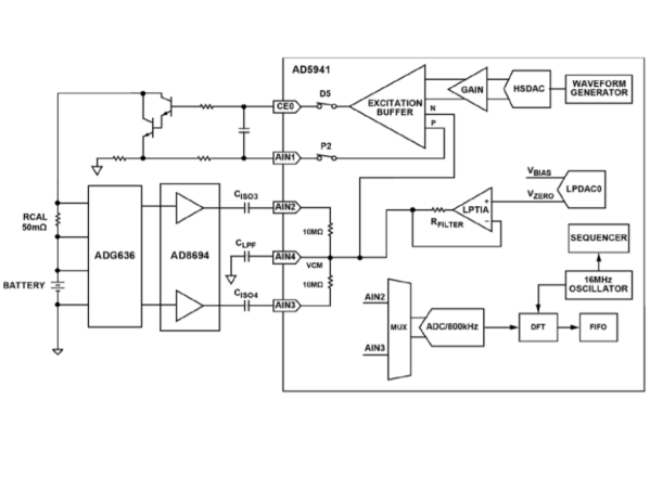
The circuit shown in the figure below is an electrochemical impedance spectroscopy measurement system used to characterize lithium-ion and other types of batteries. EIS is a safety perturbation technology used to detect processes occurring inside electrochemical systems. The system measures the impedance of a battery in a certain frequency range. These data can determine the battery’s operating state (SOH) and state of charge (SOC). The system uses an ultra-low power analog front end (AFE) designed to stimulate and measure the current, voltage or impedance response of the battery.

Simplified circuit functional block diagram

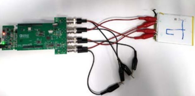
Complete EIS battery system
As aging will cause battery performance degradation and irreversible changes in battery chemical composition, the impedance increases linearly with the decrease in capacity. Using EIS to monitor the increase in battery impedance can determine the SOH and whether the battery needs to be replaced, thereby reducing system downtime and maintenance costs. ADI’s impedance and electrochemical front-end AD5941 is the core of the EIS measurement system.
AD5941 is a high-precision, low-power analog front end (AFE) designed for portable applications that require high-precision, electrochemical-based measurement techniques (such as current, volt-ampere, or impedance measurement). AD5941 consists of a low-bandwidth loop, a high-bandwidth loop, a high-precision analog-to-digital converter (ADC) and a programmable switch matrix. Among them:
● The low-bandwidth loop is composed of low-power, dual-output digital-to-analog converters (DAC) and low-power transimpedance amplifiers (TIA). The former can generate VZEROAnd VBIAS, The latter can convert the input current into voltage.Low-bandwidth loops are used for low-bandwidth signals, where the frequency of the excitation signal is less than 200 Hz, such as battery impedance measurement
● High bandwidth loop is used for EIS measurement. The high-bandwidth loop includes a high-speed DAC to generate an AC excitation signal when making impedance measurements. The high-bandwidth loop has a high-speed TIA to convert a high-bandwidth current signal up to 200 kHz into a voltage that can be measured by the ADC.
● The switch matrix is a series of programmable switches that allow external pins to be connected to the high-speed DAC driver amplifier and the high-speed TIA inverting input. The switch matrix provides an interface for connecting external calibration resistors to the measurement system. The switch matrix also provides flexibility in electrode connection.
Since the impedance of the battery is usually in the milliohm range, a calibration resistor R of similar value is also requiredCAL. RCALSmaller, the external gain stage uses AD8694 to amplify the received signal. The AD8694 has ultra-low noise performance and low bias and leakage current parameters, which are essential for EIS applications. In addition, in RCALSharing an amplifier with the actual battery helps to compensate for errors caused by cables, AC coupling capacitors, and amplifiers.
Its working principle is that AD5941 uses waveform generator, high-speed DAC (HSDAC) and excitation amplifier to generate sine wave excitation signal. The frequency is programmable, ranging from 0.015 mHz to 200 kHz. The signal is applied to the battery through the CE0 pin and the external Darlington pair transistor configuration. This circuit requires a current amplifier, because the upper limit of the current that the excitation buffer can generate is 3 mA. A typical battery requires up to 50 mA.
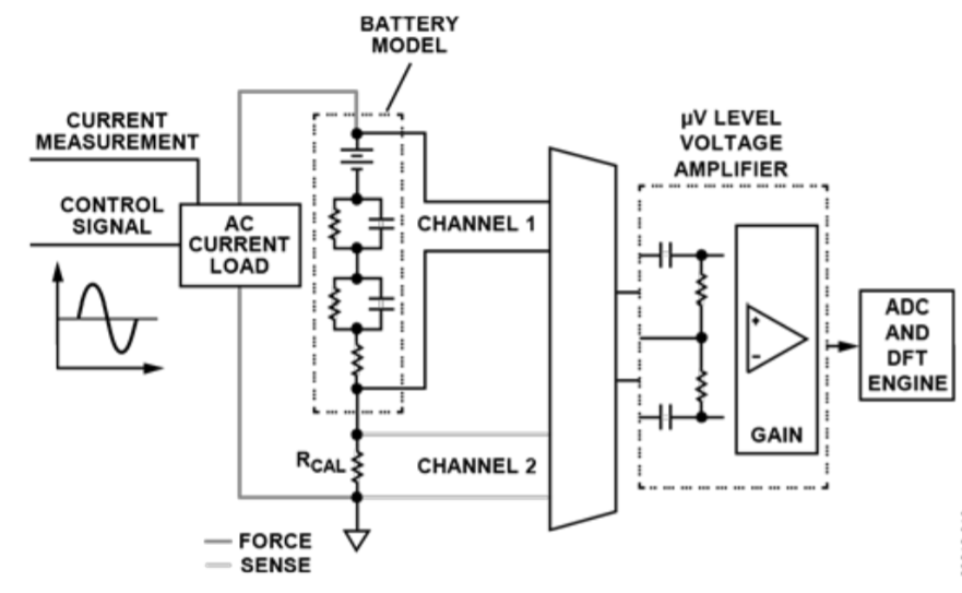
There are two voltage measurement phases in this process. First, measure RCALThe pressure drop on it. Second, measure the battery voltage. The voltage drop across each component is very small in the microvolt range (μV). Therefore, the measured voltage is sent through an external gain stage. The output of gain amplifier AD8694 is sent directly to ADC on AD5941 chip through pin AIN2 and pin AIN3. By using Discrete Fourier Transform (DFT) hardware accelerometer, DFT is performed on ADC data, where real and imaginary numbers are calculated and stored in the data FIFO for RCALVoltage measurement and battery voltage measurement. ADG636 pair battery and RCALIt is multiplexed and output to the AD8694 gain stage.

EIS measurement chart
EIS uses a proportional measurement method. In order to measure the unknown impedance (ZUNKNOWN), in the known resistance RCALApply an AC current signal to the device and measure the response voltage VRCAL. Then at unknown impedance ZUNKNOWNApply the same signal on and measure the response voltage VZUNKNOWN. Perform a discrete Fourier transform on the response voltage to determine the real and imaginary values of each measurement. The unknown impedance can be calculated using the following formula:

The electrochemical internal resistance map test method is to inject a certain current to change the voltage of the battery to analyze the current situation of different frequencies. Through its voltage and current characteristics to reflect the changes in the internal resistance of the entire battery, it can basically Reflects the changes in the electrochemical characteristics of the battery. It is a critical parameter for the life prediction of the entire battery, including whether the battery can work safely. This kind of electrochemical internal resistance test is also a relatively complicated technology. ADI provides a relatively simple and low-cost method based on high-precision, impedance and electrochemical front-end chip AD5941, which can estimate the battery electrochemistry. Internal resistance.
The Links: FZ1200R12KF5 G121XN01V0

0 Comments for “Accurately monitor the status of lithium batteries based on electrochemical impedance spectroscopy measurement methods”