“In the automatic control of tracked locomotives, it is necessary to accurately measure the position of the mobile locomotive. For this reason, a set of inductive wireless position detection system is designed. The system is based on the principle of electromagnetic induction, and obtains the position of the mobile locomotive by detecting the phase and amplitude of the induced electromotive force between the antenna box coil and the encoding cable.
“
Authors: Cheng Wangbin, Chen Jin
In the automatic control of tracked locomotives, it is necessary to accurately measure the position of the mobile locomotive. For this reason, a set of inductive wireless position detection system is designed. The system is based on the principle of electromagnetic induction, and obtains the position of the mobile locomotive by detecting the phase and amplitude of the induced electromotive force between the antenna box coil and the encoding cable. The basic framework of the induction wireless position detection system is introduced, the basic working principle of the system is explained, the position detection formula is deduced, the position detection circuit model is designed, and the wireless induction position detection experiment is carried out. The results show that the inductive wireless position detection system has high detection accuracy and strong anti-interference ability, which can meet the requirements of precise positioning of mobile locomotives.
0 Preface
The automatic positioning of industrial locomotives is the basis of the automatic operation of locomotives. It requires detection devices to accurately, quickly and reliably detect the running position of the locomotive. Induction wireless technology is a new industrial application technology developed in Japan in the late 1970s. It is mainly developed for the automation of large-scale mobile locomotives in industrial production. Inductive wireless position detection is to detect the phase and amplitude of the induced signal through electromagnetic induction between the induction coil installed in the antenna box on the mobile locomotive and the coded cable laid next to the ground track, so as to obtain the mobile locomotive Location. Inductive wireless position detection is characterized by good repeatability, high detection accuracy, good safety, strong applicability, strong anti-interference, and high reliability.
1 The overall structure of the induction wireless position detection system
In the automatic control system, two basic problems must be solved: a. Reliable data communication between the control and controlled parties; b. Location detection of the location of the mobile locomotive. The induction wireless position detection system integrates induction wireless data communication and position detection into one system. It consists of a position signal generator, an encoding cable, an induction antenna, and a position detector. Among them, the induction antenna box is installed on the mobile locomotive to move randomly, and always keep a distance z from the encoding cable; the encoding cable part is composed of the encoding cable, the connecting cable, and the matching impedance. The block diagram of the inductive wireless position detection system is shown in Figure 1.
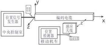
Figure 1 Block diagram of the induction wireless position detection system
2 Research on inductive wireless position detection method
2.1 APD detection
General position detection (APD) principle: The ground station of the central control room transmits the carrier signal to each detection position in the coded cable in a certain order in a time-sharing manner. The induction coil in the antenna box is used as the receiving coil, and the position detector on the mobile locomotive detects Receive the carrier signal received by the coil, and then get the position of the receiving coil. The tiled diagram of the APD detection structure is shown in Figure 2.
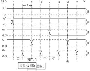
Figure 2 APD detection structure tile diagram
In the time periods t0, t1, t2, t3, and t4, carrier signals are sent to the transmission pair lines R, R’, G2, G1, and G0, respectively, and not sent in the time period t5. There are two receiving coils in the antenna box on the car: receiving coil 0 and receiving coil 1. APD detection is to obtain the APD position from the phase of the signal induced by the receiving coil 0. In the t0 time period, the coil 0 induces the signal sent by the R line, which is called the R signal; in the t1 time period, the coil 0 induces the R’signal, and the R’signal is inverted from the R signal, which is recorded as =1, as Start bit; in the t2 time period, coil 0 induces the signal sent by the G2 line, G2=0 or 1, depending on the position of the receiving coil 0. If the center line of the receiving coil 0 is at the positions of ①, ②, ③, and ④, the phase of the receiving signal of the receiving coil 0 is shown in Figure 3.
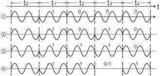
Figure 3 Schematic diagram of the received signal phase
Since each G-pair line crosses according to the Gray code rule, the result data G2 G1 G0 of the phase comparison is a set of Gray codes. Let the decimal number corresponding to the Gray code G2 G1 G0 be g, that is, g is the APD position data. Demodulate the binary absolute phase shift keying (2PSK) modulation signal in Figure 3, and use =1 as the starting bit, then: at the position ① in Figure 2, G2 G1 G0=000, g=0; At position ②, G2 G1 G0=010, g=3; at position ③, G2 G1 G0=110, g=4; at position ④, G2 G1 G0=111 or 101, g=5 or 6. The available APD position formula is:
![]()
2.2 HRPD test
The principle of high-resolution position detection (HRPD): The position signal generator detects the signal amplitude induced by the receiving antenna coil 1 on the transmission pair G0 and the carrier respectively, and obtains the HR-PD position through calculations. Taking the center line of coil 1 as the position of the moving locomotive, the area between the two crossings of the transmission pair is called K area K=I, II, III…); the center line of coil 1 deviates from G0 and the distance between the center line of the area where the transmission pair is located is respectively d0, d1, obviously d0+d1=r. HRPD position detection is shown in Figure 4.
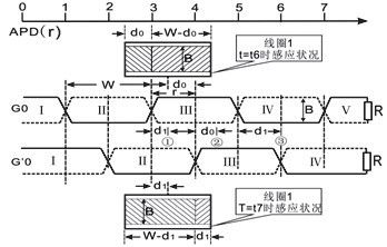
Figure 4 HRPD detection tiles
In the t6 time period, when the position signal generator sends a carrier wave to the G0 transmission pair line, the induction area of the III area of G0 to coil 1 is: S=(W-d0)xB, and the induction area of the II area of G0 to coil 1 is S=d0×B. Since the phases of the induced signals generated by the coil 1 in the II and III areas are opposite, the effective induction area of the coil 1 is S=(W-d0)×B-d0×B=2(r-d0)×B. Suppose the maximum induction area of coil 1 Smax=W×B=2r×B, and the maximum amplitude of the corresponding induction signal is Amax (y, z), then:

In the t7 time period, when the position signal generator sends a carrier wave to the transmission pair line, the same analysis is performed on the induction signal of the coil 1, and the result is:


make


And there are:
(1) The center of coil 1 is located at the left half of the two intersections of G0 (position ① in Figure 4). The detected APD position data g here is an odd number, then HRPD=d1=P0×r.
(2) The center of the transmitting coil is located in the left half between the two intersections (position ② in Figure 4). The APD position data g detected here is an even number, then HRPD=d0=P1×r.
In summary (1) (2), the high-resolution position HRPD and the integrated position ADD are:

2.3 Example analysis of inductive wireless location detection
Assume r=10cm. The coil 1 of the antenna box is located at the positions ①, ②, and ③ in Figure 4 respectively. For the convenience of analysis, only three pairs of G transmission lines are written, and there are:
(1) Coil 1 is in position ①
If G2 G1 G0=010, that is, g=3, then APD=2×r=30cm.
If the measured amplitude of the transmission pair G0, is: A(G0)=0.38Amax, A()=0.62Amax,
Then by formulas (7) ~ (10): P0=0.38, P1=0.62, HRPD=P0×r=3.8cm; ADD=APD+HRPD=33.8cm.
(2) Coil 1 is in position ②
If G2 G1 G0=011, that is, g=4, then APD=g×r=40cm.
If the measured amplitude of the transmission pair G0, is: A(G0)=A()=0.5Amax,
In the same way, we can get: P0=P1=0.5, HRPD=P1×r=0.5×10cm=5cm; ADD=APD+HRPD=45cm.
(3) Coil 1 is in position ③
A(G0)=Amax, A()=0, P0=1, P1=0 can be obtained. Since A(G0)=0, the G1 induction signal is compared with the reference signal, and the phase is the same (that is, 0) or opposite (that is, 1). Therefore, G2 G1 G0=111 or G2 G1G0=101, that is, g=5 or 6. Then there are:
1) Take g=5, then APD=g×r=5×10cm=50cm, HRPD=P0×r=1×10cm=10cm, ADD=APD+HRPD=50cm+10cm=60cm.
2) Take g=6, then APD=g×r=6×10cm=60cm, HRPD=P1×r=0×10cm=0cm, ADD=APD+HRPD=60cm+0cm=60cm.
To sum up 1) and 2), both get: ADD=60cm.
3 Induction wireless position detection circuit
The circuit block diagram of the induction wireless position detection system is shown in Figure 5. When the ground station of the central control room starts to send the carrier signal, DCD=1; after the CPU detects DCD, it detects the 2PSK demodulation output, and uses the first 1 as the start bit for serial data reception to obtain the APD position data g; During G0, start A/D1 and A/D2, read the signal amplitude A (AN0) received by receiving coil 0 and the signal amplitude A (AN1) received by receiving coil 1 from A/D1 and A/D2, and set each Substituting the data into formulas (5) ~ (8), the position ADD of the mobile locomotive can be obtained.
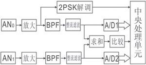
Figure 5 Block diagram of induction wireless position detection circuit
4 Induction wireless position detection experiment
Experimental method: Find any place in the coded cable and move the antenna box repeatedly until it detects that A() is the smallest. At this time, the displayed address is 29.000m, and this is the actual 29.000m. Then move the antenna box around this area every 2mm, record the A(G0) and A() detected each time, and calculate the position data: HRPD, ADD based on the detected data. In the same way, do the same test at 30.000m. Part of the test data and calculation results are shown in Table 1.
Table 1 The measured data and calculation results of the position detection part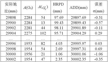
The experimental results explain: a. The deviation between the actual measured position and the theoretical corresponding position is small; b. The position detection accuracy is high, and the resolution is 2mm. In order to reduce the error, in actual application, the data of multiple experiments is made into a table, and the HRPD is calculated and corrected.
5 Conclusion
The inductive wireless position detection system designed in this paper uses the electromagnetic induction of the transmission pair and the antenna box coil in the coded cable to realize the position detection of the mobile locomotive. It adopts a non-contact absolute position detection method, which overcomes the traditional wired and wireless position. The detected defects can meet the requirements of precise positioning of mobile locomotives. At present, the induction wireless position detection technology has been applied to the position detection of the coke oven industrial mobile locomotives for automatic control of the coke pushing car, quenching car, coal loading car and dust removal car. The actual application effect is good, and the automation is basically realized. .
The Links: LM32008F G121EAN010

0 Comments for “Application scheme of induction wireless position detection system based on electromagnetic induction technology”