“The UART interface is used for system software update, so users will generally seldom use this function, thus avoiding the external I/O connector taking up space and adding additional costs. In order to facilitate debugging and development, designers usually prefer to let such applications share data channels with the USB port.
“
Author: Han Xiaoyong
Application background
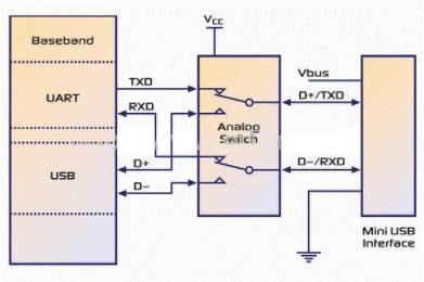
figure 1
The UART interface is used for system software update, so users will generally seldom use this function, thus avoiding the external I/O connector taking up space and adding additional costs. In order to facilitate debugging and development, designers usually prefer to let such applications share data channels with the USB port.
Another popular trend is to share the micro USB connector between the USB signal and the audio signal. Figure 2 shows the most commonly used application sharing methods.
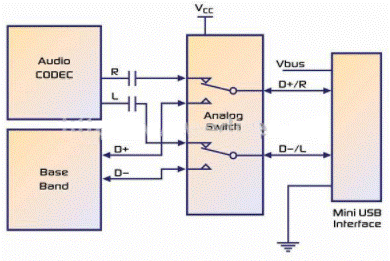
figure 2
In this application, the negative signal will appear after the audio signal path through the capacitor. But ordinary single-supply systems cannot receive negative signals, which may cause unexpected leakage or damage. In some cases, the analog switch can tolerate negative signals without crashing, but the negative swing of the signal will produce unpredictable channel crosstalk, greatly reduce the OFF isolation performance, and may even cause the channel that should be closed to be in an open state.
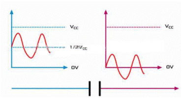
image 3
Challenges of low-power robust I/O design
There is a hidden concern in UART/USB sharing applications, that is, the signal level may exceed the power supply voltage of the internal system. The I/O voltage of the battery-powered device power supply is usually up to 3.3V. If we use this I/O voltage as the power supply for the analog switch, the USB low-speed/full-speed signal level is between 3.0 and 3.6V. At this time, there is a risk that the input signal level will exceed the power supply voltage when the system is working. Another problem is how to protect the system when it is in a “power-off” state. Usually, this requires a stable power supply to achieve the high impedance state of the analog switch.
There are two solutions to these problems. One is to use the battery power supply as the analog switch VCC, but this depends on the discharge limit of the system, that is, if the system allows the battery discharge voltage to be below 3.6V (unfortunately this is often the case), the first problem is still not solved . In addition, most of the time, the battery power supply voltage is higher than the system’s I/O voltage (3.3V), which means that the logic selection pin level may be much lower than the power supply voltage, which may cause a large current leakage. . Therefore, in order to prevent current leakage, a level shifting IC needs to be added to the logic selection pin. Figure 4 illustrates this.
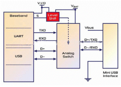
Figure 4
The second solution is shown in Figure 5.
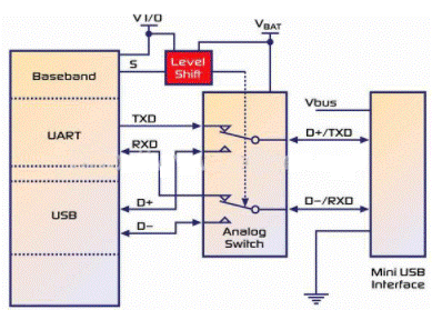
Figure 5
This power solution can ensure that the system always has power at any time (regardless of power-on or power-off, and whether the USB cable is plugged in). The only limitation of this solution is the cost issue caused by additional components. And the last problem of this application is often overlooked: the requirement of USB short-circuit withstand capability.
Short circuit withstand ability
The USB transceiver must be able to withstand at least 24 hours of continuous short-circuit from D+ and/or D- to VBUS, GND and other data lines, or the cable shielding shell at the connector plug, without degrading performance. It is recommended that the transceiver design should be able to withstand such uncertain short-circuit faults. In the case of a short circuit, the device must not be damaged when the transmission and reception time are divided by half (all supported speeds). There is a symmetrical signal during transmission, which switches between high and low levels. When VBUS is at its maximum value (5.25V), the short-circuit withstand capability of the system must be guaranteed. It is recommended that these AC and short circuit requirements be used as the qualification criteria for the long-term reliability of the device. That is, the USB2.0 specification.
Another important factor to consider is ESD (electrostatic discharge) protection. Since the I/O ports are highly susceptible to ESD, it is strongly recommended to provide additional ESD protection. If the USB signal channel is high-speed (480M bps), the parasitic capacitance should be less than 1pF to minimize the bus load, otherwise it will adversely affect the eye diagram test results. In audio/USB sharing applications, there is also the challenge of negative wobble signals. One way to avoid this is to put a capacitor in the headphone cable. However, in order to obtain better audio low-band response, the capacitor should be as large as possible, which increases the size and cost. Another way to solve this problem is to select a negative swing audio amplifier in the design (the audio output signal swings up and down directly based on GND).
Fairchild Semiconductor’s innovative multimedia switches FSA201 and FSA221 solve the above-mentioned problems (FSA201 is used for full-speed USB, and FSA221 is used for high-speed USB).

Image 6
FS USB source FS USB source
AUDIO CODEC audio codec
Device ID recognition Device ID recognition
MINI USB CONNECTOR
Using FSA201 and FSA221, the internal logic control can automatically switch power between VAUDIO and VBUS, and meet the USB short-circuit withstand capability requirements. When VAUDIO=0, these switches can automatically make all ports in a high impedance state. In addition, the R/L channel can receive negative swing signals as low as VAUDIO-7.0V (if Vaudio=3.3V, 3.3V”-3.7V signals) with extremely high isolation. It has low ICCT characteristics, allowing VAUDIO has a higher power supply voltage, which can realize normal I/O voltage level control signal input with leakage less than 10uA. These switches integrate 8KV ESD protection function (HBM mode), which is very suitable for I/O sharing applications. All of these Features greatly simplify the I/O design of the system, while protecting the ports from various damages.
Summarize
As the market trend is to integrate more and more multimedia functions into portable devices that are becoming slimmer and smaller, analog switches are taking on new roles different from the past in mixed-signal conversion, system protection, and intelligent detection. These switches are not only important bridges connecting different modules in portable applications, but also have the functions of signal sharing, isolation and protection. The new generation of analog switches, such as FSA201 and FSA221, provide designers with great advantages. Through these switches that integrate high-performance, robust ESD protection and ultra-compact packaging, designers can simplify designs, reduce component count, reduce costs, and bring products to market faster. As a result, designers can spend more time designing, and no longer have to worry about choosing different chipsets and updating processors to cope with the tricky design problems caused by port sharing.
The Links: 2RI100E-060 LM150X08-A4K8

0 Comments for “Design and application scheme of analog switch in portable equipment”