“This article adopts the ultrasonic mobile robot navigation design method, adopts a new type of high-precision ultrasonic sensor, and uses software methods to overcome the problem that it is not conducive to detecting echo in ARM9. It has been successfully applied to the trajectory control of mobile robots, so that The immediacy of walking and image acquisition has been greatly improved.
“
Introduction: This article uses ultrasonic mobile robot navigation design method, adopts a new type of high-precision ultrasonic sensor, and uses software method to overcome the problem that it is not conducive to detecting echo in ARM9. It is successfully applied to the running trajectory control of mobile robot. The robot has achieved a great improvement in the immediacy of walking and image acquisition.
1 Introduction
In the project development, the SRF05 ultrasonic sensor imported from the United Kingdom is used. Its echo feedback and ranging method are special compared with the commonly used ultrasonic sensors. It is also slightly difficult to implement in ARM, but the sensor has a high accuracy of 1cm. , Therefore, the infrared ranging module used for short-distance measurement is removed with this sensor, which saves hardware resources.
The smallest system of the robot is a touch screen module, an ultrasonic module, a camera image acquisition module, and a DC motor closed-loop control system. Ranging is the most important part of the entire system, which directly affects the accuracy of the motor running distance, in the effective range Image acquisition control inside. The entire system is completed on ARM9 and Linux platforms, and each module is implemented in a device-driven way to make the control of the module more convenient.
2 SRF05 Ultrasonic Ranging Method
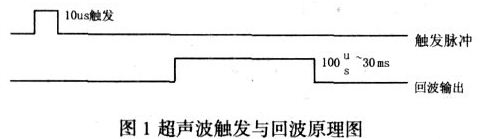
Provide a 10us pulse to trigger the ultrasonic sensor. SRF05 will send out 8 cycles of 40khz overclocking pulses. At this time, the level on the echo port changes to high in the echo. At this time, the timer starts timing and waits until the echo becomes The low level proves that there is an obstacle, and the timing stops at this time. The width of the high pulse is proportional to the distance of the distance measurement. The effective distance measurement range of the ultrasonic wave is 1cm~4m. Therefore, if there is no obstacle or the obstacle is greater than 4m, the echo will still The time of the timer when it becomes low level is 30ms, so the period of the timer should be greater than 30ms during ranging, so that the ranging can be effective.
The principle is shown in Figure 1.
3 Implementation of Ultrasonic Ranging Software
Figure 2 shows the flow chart of ultrasonic ranging.
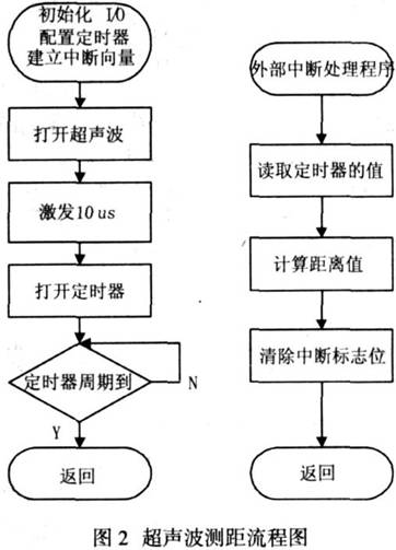
3.1 Collection method of echo detection
Ultrasonic echo detection is a difficult point, because only one trigger mode can be set for a port setting interrupt in ARM. If it is set to rising edge trigger, the timer timing can be turned on but the falling edge cannot be captured, so the timer cannot be turned off. It can’t measure distance, so it can be realized by software. First set up two time delay functions usdelay() and msdelay(), so that you can wait for the ultrasonic trigger to turn on the timer after the high pulse 10us is given, and set an external interrupt eint1 to connect to the echo port of the ultrasonic sensor and set it to drop Edge trigger, wait for the falling edge to turn off the timer. The read value is the length of the pulse width, and then the distance is calculated according to the distance of the obstacle = (ECHO high level time) * sonar speed/2. The relationship between v and temperature in the air: v=331.5√1+T/273 m/s, T is the temperature in Celsius. Under normal circumstances, the speed of ultrasound is similar to the speed of sound, which is about 343.2m/s under the influence of indoor temperature.
3.2 The realization of ultrasonic trigger
Use a digital oscilloscope to accurately design a software timing function usdelay, the specific implementation is as follows.
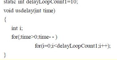
Then usdelay(1) is 10us, this function is used to continue 10us after giving the excitation high pulse and then turn off the pulse.
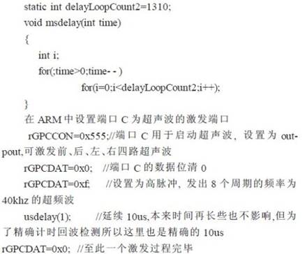
Also design a msdelay() to control the time value of the entire ranging period.
msdelay(1000) is used to delay 1s in the main function number, so that the timer can have enough echo detection time and will not cause interference to the other three ultrasonic signals.
As follows.
3.3 The realization of ultrasonic echo detection
Echo detection needs to use timer and external interrupt to calculate the pulse width time. External interrupt is connected to ultrasonic echo and set as falling edge trigger. The initialization of the timer is as follows.
rTCFG0=0x9595; //The prescaler value is 95
rTCFG1=0x00000; //Segment value 1/2
rTCNTB0=10000; /
According to T=[TCNTB0*(TCFG0+1)*(1/TCFG1)]/50MHZ gives the timer period of 60ms, which is enough to calculate the echo time in this time period.
External interrupt 1 is initialized as follows
rGPFCON=0xaa; //GPF1 is set to EINT1
rINTMOD=0x0; //Set as normal interrupt
rGPFUP=0xf; //Disable GPF0 pull-up resistor
pISR_EINT1=(unsigned) Eint1Handler; //Establish interrupt vector
EnableIrq (BIT_EINT1); //Enable interrupt
rEXTINT0 =0x492; // EINT1 falling edge trigger
According to T=[TCNTB0*(TCFG0+1)*(1/TCFG1)]/50MHZ gives the timer period of 60ms, which is enough to calculate the echo time in this time period.
3.4 Computer distance in external interrupt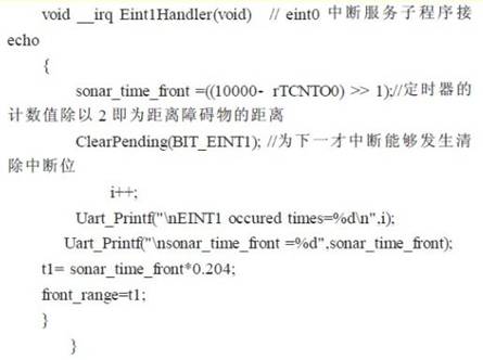
3.5 Cyclic control and polling ranging
Due to the interference between the ultrasonic waves, the polling method is used to turn on the ultrasonic waves one by one, and only measure one at a time. This can effectively avoid interference. In order to improve the real-time performance, the timer period can be controlled, for example, set to 35ms, so that the four-way ultrasonic polling One time is about 140ms, which is enough to meet real-time requirements.
4 Realization of robot control
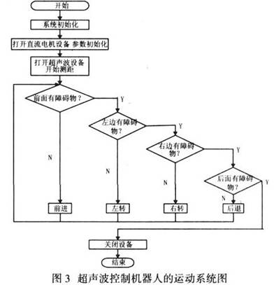
Figure 3 is the overall structure diagram of the closed-loop system of controlling the robot’s DC motor using ultrasonic feedback information.
The ultrasonic sensor in the linux system is a read-only character device. The specific application is to open the ultrasonic device under the application, and then measure the distance in the drive, and the measured data is transmitted to the application. The application has an ultrasonic obstacle avoidance algorithm. The algorithm judges the position of the obstacle to the DC motor control signal for obstacle avoidance navigation.
The graphical interface in the touch screen contains the command settings of the robot, you can set the running speed, the image acquisition and the opening and closing of the ultrasonic module, whether to open the robot fuzzy algorithm running track or use the ordinary PID adjustment, which makes the robot have many options to choose .
Each behavior of the robot is based on the value measured by the ultrasonic sensor and the instantaneous speed of the current robot operation to give the running time. When encountering an obstacle (0-30 us, equal to 30 microseconds, it will reach the ultrasonic wave The maximum detection distance of the camera), turn on the camera image acquisition module, then the camera will take the image of the obstacle, and use the wireless MODEM to send the image back to the control computer, so that the user can know what obstacle is ahead, and the system realizes the movement The robot’s autonomous obstacle avoidance and the function of collecting obstacle information can be used to detect unknown environments.
5 Conclusion
In this paper, a new type of ultrasonic sensor is used to realize ultrasonic distance measurement on a mobile robot based on ARM9 and embedded linux, and the ultrasonic sensor is used to control the motion system and the image acquisition system. The robot has been successfully applied to the development of this project and achieved good results.
The Links: C070FW02-V0 RM500CZ-M
0 Comments for “Design method of mobile robot navigation using ultrasonic”