“The biggest feature of the voice system is to achieve backward compatibility with existing communication equipment. Users do not need to replace the existing communication equipment without Bluetooth function, they can enjoy the convenience of wireless communication. How to make existing equipment and new Maintaining a smooth transition or seamless connection between technical products is a problem that every R&D staff should emphatically consider when developing products. It is based on the above considerations that this Bluetooth voice system was developed to promote Bluetooth products as soon as possible. To the market.
“
Author: Zhou Zheng; Chen Jing
The Bluetooth chip ROK 101 007 introduced by Ericsson is a radio frequency/baseband chip suitable for short-distance wireless communication. It has high integration and low power consumption. It is fully compatible with Bluetooth protocol Version 1.1 and can be embedded in any device that requires Bluetooth functionality. Medium. The chip includes functional blocks such as baseband controller, wireless transceiver, and flash memory, which can provide functions up to the HCI (host control interface) layer. In addition, the chip also provides USB, UART and PCM interfaces for communication with the host ; And it supports Bluetooth voice and data transmission, and the output power meets the requirements of Bluetooth secondary operation.
1 Introduction to internal structure and functional blocks
ROK 101 007 includes five functional blocks: wireless transceiver (PBA 313 01/2), baseband controller, flash memory, power management module, and clock, as shown in Figure 1.
1.1 Wireless transceiver PBA 313 01/2
PBA 313 01/2 is a short-distance microwave frequency radio frequency transceiver that works in the 2.4~2.5GHz ISM frequency band. It uses GFSK modulation. The maximum TX&RX data transmission rate is 1Mbit/s. It can be used in 79 channels (2.402 Frequency hopping (1600 channels/s) between ~2.480GHz), the channel bandwidth is 1MHz, and the frequency deviation is between 140kHz and 175kHz. It meets Bluetooth secondary operation, the maximum output power is 4dBm, and no power control is required. Installation After the antenna, the transmission distance can reach 10m, which is in line with the FCC and ETSI standards of the ISM band. BA 313 01/2 is based on Radio ASIC and integrates a loop filter, a voltage-controlled oscillator, an antenna filter, a transceiver controller, and a transmission The six operating components such as the receiver and receiver are shown in Figure 1. The functions of each component are as follows:
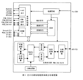
①Radio ASIC completes signal modulation and demodulation.
②Loop filter, voltage-controlled oscillator and Radio ASIC form a phase-locked loop. The loop filter filters out the high-frequency components and noise of the error voltage output by the Radio ASIC to ensure the required performance of the loop and increase the system’s stability.
③The transceiver controller coordinates the work of the receiver (RX) and transmitter (TX) to ensure the full duplex transmission of Bluetooth.
④The antenna filter performs band-pass filtering on the radio frequency signal. The pin ANT (T2) is the antenna interface, and an antenna with an impedance of 500Ω should be connected.
1.2 Baseband Controller
The baseband controller is a functional block based on ARM7-Thumb, which controls the wireless transceiver through the UART or USB interface. The baseband controller is responsible for processing the underlying link layer functions, such as the selection of the frequency modulation sequence.
1.3 Flash
The flash memory stores the Bluetooth firmware in a binary code format, which can exchange data, addresses and control signals with the baseband controller. The Bluetooth firmware includes a link manager and a host control interface (HCI).
The link manager implements the link management protocol (LMP), which is responsible for handling the underlying link control. Each Bluetooth device can communicate point-to-point with the link manager of another Bluetooth device through LMP. HCI provides access to the host Baseband controller, link manager and hardware status and control register command interface. The host controls the Bluetooth interface through a series of commands provided by the HCI driver; after the HCI of the Bluetooth firmware receives the command, an event will be generated and returned to the host for use Indicates the status change of the interface. There are three types of data transmission between the host and HCI:
• The HCI command packet is sent from the host to the Bluetooth HCI.
• The HCI event packet is sent from the Bluetooth HCI to the host.
• HCI data packets can be sent from the host to HCI or from HCI to the host, including connectionless (ACL) data and synchronous connection (SCO) data.
The HCI transport layer defines how each type of data is encapsulated and how to be multiplexed through the interface. ROK 101 007 supports two HCI transport layers: UART transport layer and USB transport layer.
1.4 Power Management Module
The module provides the power required by the chip. The typical value of Vcc is 3.3V.
1.5 Clock
The module has a built-in clock with a frequency of 13MHz. The clock is generated by a crystal oscillator to ensure that the timing accuracy is within 20ppm.
2 Introduction of chip interface and main pins
When ROK 101 007 is interconnected with the host or other equipment, there are three interface methods (see Figure 1).
2.1 USB interface
The USB interface of ROK 101 007 conforms to the USB1.1 specification. Through the two-way port D+&D-, the data transmission can reach 12Mbps. When the USB interface is used to communicate with the host, ROK 101 007 is a USB slave device. The management related to the interface The feet have:
• D+(B1)&D-(B2) is used for data transmission.
• Wake up (B4) & Detach (C1) is used to interconnect with a laptop, and can be used to control the status of the laptop. When the host is in power-down mode, if the Bluetooth device receives a request to establish a connection, the Wake up signal will “wake up” “Host. The host can indicate that it is in the “suspend” mode through the Detach signal.
2.2 UART interface
ROK 101 007’s UART interface complies with the industrial standard 16C450, and supports the following wave rates (unit: bits/s): 300, 600, 900, 1200, 1800, 2400, 4800, 9600, 19200, 38400, 57600, 115200, 230400 and 460800 Use an HCI command customized by Ericsson: HCI_Ericsson_Set_Uart_Baud_Rate can change the wave rate of the UART interface. The interface has a 128-byte first-in-first-out (FIFO) buffer. The four pins related to the interface are:
•TxD (B5) & RxD (A5) are used to send and receive data.
•RTS (A6) & CTS (B6) are used for data flow control.
2.3 PCM voice interface
The standard PCM voice interface sampling rate is 8kHz. The voice coding method can use CVSD (continuously variable slope delta modulation), μ law (8bit) or A law (8bit). Considering the robustness of the coding, CVSD should be selected first.
The pin signals related to the PCM voice interface are:
• CM_SYNC (A3) Set the sampling rate of PCM data.
• CM_OUT(A2)&PCM_IN? A1 Receive or send voice coding signal. The direction of these two pin signals can be adjusted by programming.
3 Introduction to the Bluetooth Voice System of the Wireless Network Laboratory of Beijing University of Posts and Telecommunications
A set of Bluetooth voice system was developed using ROK 101 007 chip, which enables wireless voice transmission between various existing communication devices (mobile phones or fixed phones) and Bluetooth headsets, thereby realizing the backward direction of Bluetooth technology to existing devices compatible.
3.1 System composition
The system consists of a Bluetooth adapter and a Bluetooth headset. The Bluetooth adapter is connected to the existing communication device (mobile phone) to realize the signal conversion between Bluetooth and the phone; there is a PTT button on the Bluetooth headset for answering and ending calls. A Bluetooth wireless link can be established between the Bluetooth adapter and the Bluetooth headset to transmit voice, data or control signals.
The working process of the system is as follows: the Bluetooth adapter is the main party. After power on, it enters the query mode and automatically searches for the surrounding Bluetooth devices (earphones). If there is a Bluetooth headset nearby, the main party initiates a connection request and establishes a Bluetooth data connection (ACL connection) with it Then the master and slave enter the standby mode. When there is an incoming call or a call, the master informs the slave. If the slave decides to connect to the call, the master establishes a voice link between the master and the slave (SCO connection), and enter the call state.
Definition of key terms:
The master refers to the party that initiates the connection (the adapter in this system is the master);
The slave refers to the party receiving the connection (the headset is the slave in this system)
ACL refers to asynchronous connection link, used for Bluetooth data transmission;
SCO refers to the synchronous connection link, which is used for Bluetooth voice transmission.
3.2 Hardware circuit
The hardware structure of the Bluetooth adapter and the headset is basically the same, and the circuit block diagram is shown in Figure 2.
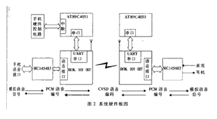
The hardware circuit is mainly composed of three modules:
The MCU control module includes the AT89C4051AT89C4051 chip and the signal light system, which completes the initialization of the system, the establishment of the Bluetooth communication link and the monitoring of mobile phone calls. The MCU is connected to ROK 101 007 through the serial port.
The voice module includes MC145483MC145483 voice codec circuit and earphone, microphone voice input and output peripheral circuit, complete the voice codec function. MC145483 is a 13-bit linear PCM codec filter, which can complete the digitization and reconstruction of voice signals, and ROK 101 007 PCM voice interface connection.
The Bluetooth module includes an Ericsson point-to-multipoint Bluetooth chip and an inverted F antenna. The chip realizes the core functions of Bluetooth communication.
3.3 Software design
The software design uses the direct programming of the HCI layer. The host sends a command to the HCI. After the HCI receives the command, it will be passed down to the LM layer. The LM is responsible for link establishment, encryption and authentication; the host receives the HCI sent Event package, according to the specific event to take corresponding processing. After the link is established successfully, the voice stream uses Continuous Variable Slope Delta Modulation (CVSD) technology to obtain high-quality audio coding.
The software process consists of four functional modules, as shown in Figure 3.
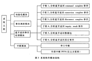
Initialization module: initialize the Bluetooth chip and various state variables;
Transaction scheduling module: According to the returned event status parameters, system transaction scheduling, jump to the return event processing module.
Bluetooth return event processing module: each subroutine handles each Bluetooth return event separately.
Interrupt module: Including external interrupt module and serial port interrupt module. The external interrupt module determines whether the phone has an incoming call (only required by the host); the serial port interrupt module is responsible for receiving and sending Bluetooth data packets and event packets.
3.4 System features and effects
The biggest feature of the voice system is that it realizes backward compatibility with existing communication equipment. Users do not need to replace existing communication equipment without Bluetooth function, they can enjoy the convenience of wireless communication. How to make existing equipment and new Maintaining a smooth transition or seamless connection between technical products is a problem that every R&D staff should emphatically consider when developing products. It is based on the above considerations that this Bluetooth voice system was developed to promote Bluetooth products as soon as possible. To the market.
After the trial, the system has clear and stable voice (which can reach the local call standard). When there is an incoming or outgoing call, the master and slave devices switch quickly, and the user does not feel the obvious delay difference. The system is cost-effective and has Very good market promotion prospects.
The Links: BSM35GP120 CM150DU-24F
0 Comments for “Design of Bluetooth Voice System Based on RF/Baseband Chip”