“This paper mainly discusses the serial communication design between PC and multiple MCS-51 microcontrollers. The software and hardware of this system have been debugged on IBM PC/XT and MCS-51 microcontrollers of DICE series, and they run well. It has been used in practical systems, and is especially suitable for small and medium-sized industrial control systems with high real-time requirements of slaves.
“
Introduction: This paper mainly discusses the serial communication design between PC and multiple MCS-51 microcontrollers. The software and hardware of this system have been debugged on IBM PC/XT and MCS-51 microcontrollers of DICE series, and they run well. The control of the simulation platform has been used in the actual system, and is especially suitable for small and medium-sized industrial control systems with high real-time requirements of slave machines.
introduction
In measurement and control systems and engineering applications, it is often encountered that multiple tasks need to be performed simultaneously, so the master-slave multi-machine distributed system has become a widely used mode in modern industry. Most of them are composed of IBM-PC microcomputer and MCS-51 one-chip computer. The single-chip microcomputer has strong functions, small size, low price, convenient development and application, and especially has the characteristics of full-duplex serial communication. It is widely used in industrial control, data acquisition, intelligent instrumentation, and household appliances. At the same time, IBM-PC just complements the defects of single-chip man-machine dialogue and weak peripheral equipment. Each MCU independently completes the data acquisition, processing and control tasks, and at the same time transmits the data to the PC through the communication interface. The PC processes, displays or prints these data, and transmits various control commands to the MCU to achieve centralized management and optimization. control.
Therefore, the communication between IBM-PC (host computer) and each MCS-51 single-chip computer (lower computer) is particularly important. This paper mainly discusses the long-distance serial communication interface and software programming between them.
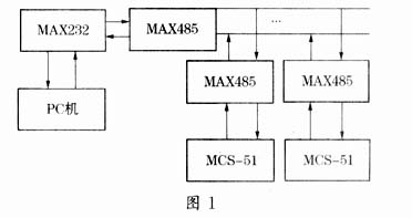
2 Hardware Design Interface
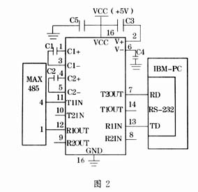
The RS-232-C serial communication interface is a standard communication protocol developed by the American Electrical Industry Association (EIA) and BELL Company, etc. It is now widely used in terminals, peripherals and computers. The standard specifies 21 signals and 25 pins, but 2 signals and 3 pins are commonly used in the communication between intelligent instruments and computers (pin 2 data input, pin 3 data output, pin 7 signal ground). It adopts bipolar negative logic signal, 0 logic signal is +3V to 12V, 1 logic signal is -3V to -12V, its maximum transmission rate is 20kbit/s, and the transmission distance is only 15m. Since RS-232 mainly completes level shifting, conversion and signal inversion, it has its own level shifting and driving chips, such as MC1488 (send) and MC1489 (receive). IBM-PC has two standard RS-232 serial ports, and its level adopts EIA level, while the serial communication of MCS-51 microcontroller is carried out by TXD (transmit data) and RXD (receive data). For full-duplex communication, their level is TTL level. In order to reliably carry out serial communication between the PC and the MCS-51 machine, a level conversion chip is required. Since MC1488 and MC1489 need ±12V, +5V power supply, the MAX232 chip with low power consumption and single power supply produced by MAXIM company is used. Because it has a power supply voltage converter, it can convert the +5V power supply into RS-232 output level The required ±10V voltage can realize the technical indicators of RS-232, and only needs +5V power supply, which brings better performance and low price for serial communication. The interface circuit diagram of MAX232 is shown in Figure 2.
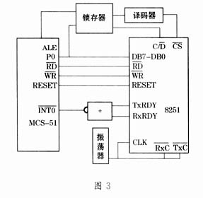
The PC is realized by the programmable serial asynchronous communication controller 8251A. By initializing the INS8251A, the serial data transmission format, speed and working mode can be controlled, so that it is consistent with the communication mode of the single-chip computer, so as to realize the communication between the PC and the single-chip computer. Communication. The connection diagram of MCS-51 and 8251A is shown in Figure 3.
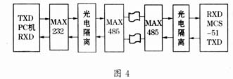
Due to the long-distance data transmission, two MAX485 chips are used for data transmission in the system, and two-stage photoelectric isolation is also used to improve the anti-interference ability of the system. The block diagram of the RS-232 communication hardware interface circuit between the single-chip microcomputer and the PC is shown in Figure 4.
3 Software programming of serial communication
3.1 The principle of master-slave multi-computer communication
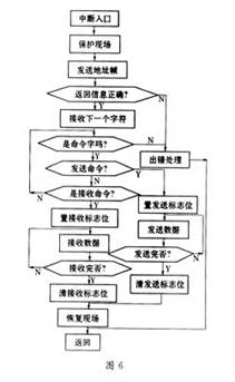
MCS-51 must work in mode 2 or mode 3 when it is used for multi-machine communication. Taking mode 3 as an example, each frame of data sent is 11 bits: 1 start bit (0), 8 data bits and 1 stop bit (1), and the additional 9th bit data in a non-multi-machine system is The parity bit is generated by TB8 of SCON at the transmitting end and transmitted to RB8 of SCON at the receiving end. It can also be set to “0” or “1” as a flag to distinguish a data frame (0 flag) or an address frame (1 flag) in multi-machine communication. In the MCS-51 multi-machine system, there are the following protocols: all the slaves are in the order state, that is, SM2=1, in order to receive the address sent by the master, when the RB8 of a frame of information is “1”, it means The host sends the address information, and all slaves receive interrupts, otherwise the interrupts are masked. When a slave enters the corresponding interrupt service routine, compares the received address with the address of the local machine, if it matches, sets its SM2=0, and sends back the local address to the host as a response, the slave will The host is connected, ready to receive the command or data information sent by the host, while other unaddressed slaves keep SM2=1 and exit their respective interrupt service routines. In this way, only the slave with SM2=0 can receive the data information sent by the master, and the separation of the address frame and the data frame is successfully realized. The addressed slave resets SM2=1 after the communication is completed, and exits the interrupt service routine, waiting for the next communication.
3.2 Multi-machine communication protocol
In order to realize the normal communication between the single-chip computer and the PC, the communication mode between them must be set correctly to ensure that both parties use the same baud rate, start bit, stop bit, parity bit, and establish communication between the two parties. response signal.
The microcontroller can work either in the synchronous shift register mode or in the UART (Universal Asynchronous Receiver/Transmitter). The communication mode of the serial port is controlled by the special function register SCON. Each control is defined as follows:
![]()
SM0, SM1: Working mode setting bit; SM2: Allow use of method 2, 3 multi-machine communication control bit; RB8: The ninth bit of the received data; TB8: The ninth bit of the transmitted data; TI: Transmit interrupt flag; RI: Receive interrupt logo. In this paper, the working mode is 3, that is, the 9-bit UART timer T1 is used as the baud rate generator, and works in mode 2. If the selected baud rate is 1200bps, the initial count value is 0E8H (SMOD=0, the clock frequency Fosc is 11.059MHz).
The asynchronous communication interface of the PC is INTEL8251A, which can set 1-bit, 1.5-bit or 2-bit stop bit, the data can be selected between 5-8 bits, the communication frequency is 0-9.6Kbps, there are parity check, frame check There are three ways of checking and overflow checking. It can be initialized by writing a certain way control word and command control word to it. Its connection with MCS-51 is as shown above, then its data port address is 0F0H, and the control port address is 0F1H. Its working status is stored in its status word register, which can be read by the CPU of MCS-51. The communication protocol is as follows: (1) The serial communication baud rate is 1200bps; (2) The frame format is 8 data bits, a start bit, and a programmable 9th bit (that is, the address/data sent and received). (3) The master and the slave follow the master-slave principle, the master selects the slave by calling, the data is transmitted in both directions between the master and the slave, and the slaves communicate with each other. The host needs to be used as an intermediary; (4) Some commands and status words for their identification should also be transmitted between the master and the slave, such as 00H for the host to send the slave to receive commands, 01H for the slave to send the host to receive commands, etc.
3.3 Communication programming ideas and implementation
The program mainly includes the host program (composed of the host main program and the communication subroutine), the slave main program and its interrupt service program. The host program mainly completes the initialization of the 8251A and the communication between the host and the slave. The block diagram of the host program is shown in Figure 5. The main program of the slave machine mainly completes the initialization of the serial port and the setting of the baud rate (should be consistent with the baud rate of the 8251A), and its interrupt program is mainly used to complete the data communication between the MCS-51 microcontroller and the PC. The block diagram of the slave interrupt service routine is shown in Figure 6.
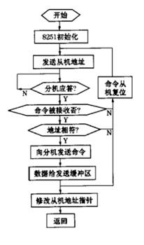
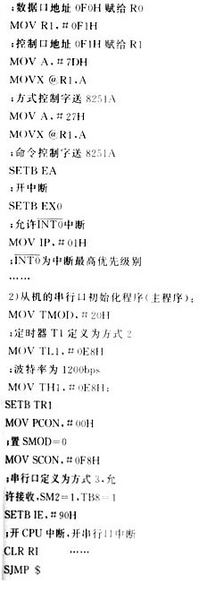
Here is a brief introduction to the initialization procedure of 8251A, set 8251A to work in asynchronous communication mode, baud rate coefficient × 1, character length of 8 bits, even parity, so the mode word is 7DH, and 8251A is set to full-duplex mode, error flag reset, so its command control word is 27H, and its corresponding initialization procedure is as follows:
MOV R0, #0F0H
4 Summary
The software and hardware of this system have been debugged on IBM PC/XT and MCS-51 single-chip microcomputer of DICE series, and it runs well. It has verified its control in the simulation platform, and has been used in the actual system, and is especially suitable for slave real-time performance. Small and medium-sized industrial control systems with higher requirements.
The Links: FF200R17KE4 EPM7512AEQC208-10N

0 Comments for “Discuss the design of serial communication between PC and multi-MCS-51 single chip microcomputer”