“SPWM is a modulation technique widely used in motor drive, inverter power and other fields. ZDS4000 series oscilloscopes rely on powerful digital filters and analysis functions to provide SPWM with an accurate analysis method that is different from traditional filter testing methods by using trend graphs.
“
SPWM is a modulation technique widely used in motor drive, inverter power and other fields. ZDS4000 series oscilloscopes rely on powerful digital filters and analysis functions to provide SPWM with an accurate analysis method that is different from traditional filter testing methods by using trend graphs.
1. Introduction to SPWM
SPWM is a PWM waveform whose pulse width changes according to a sine law. It is an extension of PWM technology and a PWM technology that can be equivalent to a sine wave effect. Widely used in motor drive, inverter power supply and other fields. The modulation principle is to use triangular wave and sine wave to modulate, and use the intersection point to determine the pulse width sequence. The modulation method is shown in the following figure:
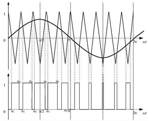
figure 1
2. Conventional testing methods
The conventional method of measuring SPWM with an oscilloscope is to use its internal software low-pass filtering function to filter out the carrier of the SPWM, and the last remaining waveform is the fundamental wave to be equivalent. As shown below:
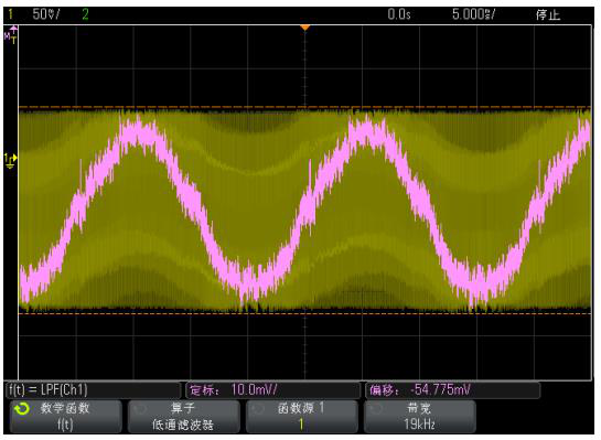
figure 2
It can be seen that after filtering, we can see that the filtered waveform is a sine wave, and users can judge whether their SPWM is correct by observing the distortion of this sine wave. But this observation is relatively crude, and many detailed errors cannot be found.
3. The method of filter + pulse width trend
It can be known from the SPWM principle that whether SPWM is correct or not depends on the law of pulse width distribution. If we can count the trend of pulse width, we can feedback the performance of SPWM more intuitively. The following figure shows the pulse width trend analysis chart of a standard SPWM test. It can be seen that the complete fundamental wave can also be restored by using the pulse width trend analysis.
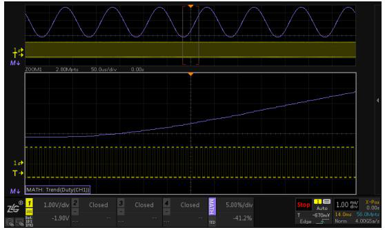
image 3
But when actually tested, this didn’t work out smoothly. This is because the waveform returned from the actual measurement has a lot of high-frequency large-signal interference noise. If the pulse width trend analysis is performed on this waveform, the true result cannot be obtained. The pulse width trend analysis result of the real waveform is shown in the following figure:
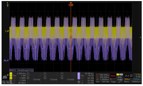
Figure 4
The ZDS4000 oscilloscope has a powerful FIR function. Through digital filtering, these high-frequency noises can be filtered out first, and then these signals without noise can be analyzed again. However, the software filter of most oscilloscopes cannot be used in series with the analysis function of pulse width trend due to insufficient processing power. We analyze the signal in Figure 2 again by using the method of filter + pulse width trend, and we can get the result as shown below.
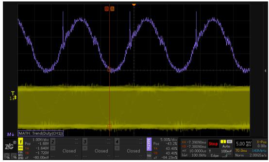
Figure 5
It can be seen that the SPWM waveform has a phase mutation, and this mutation cannot be seen in the original analysis method. Thanks to the powerful deep storage performance of the ZDS4000, we can expand the details to analyze. The expanded details are shown below:
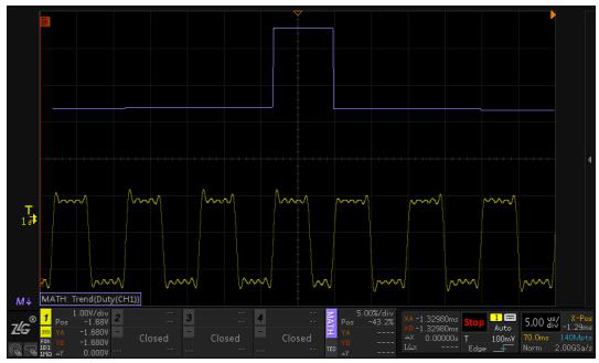
Image 6
Some users who are not familiar with SPWM may not be able to judge what is wrong in the place where the problem is, and we can use FIR for further filtering at this time. The effect after filtering is shown in the following figure:
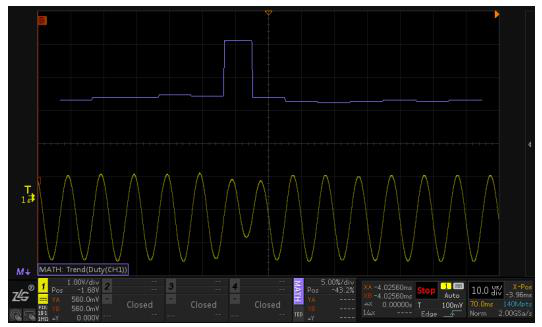
Figure 7
It can be clearly seen that where the pulse trend changes abruptly, the SPWM waveform has a sudden change in phase, which is caused by the incomplete pulse width period.
ZDS4000 not only has powerful FIR function, but also has 512M storage depth and waveform pulse width trend analysis function. Facing the SPWM test requirements in the fields of motor drive and inverter power supply, ZDS4000 uses the trend graph to provide an accurate analysis method different from the traditional filter test method, which can test and analyze the SPWM more intuitively and accurately. A new debugging experience.
The Links: LMG5320XUFC LMG7135PNFL

0 Comments for “How to analyze SPWM waveform by pulse width change trend?”