“As we all know, building a power management system is a complex project. Not only parameters such as input voltage, output voltage and current of a single device in the device should be considered, but also optimized design from the aspects of device energy efficiency, system parameters and heat dissipation. Be considerate too.
“
Author: Doctor M
Since the second industrial revolution, the development of human society has been deeply bound up with electrical energy, and electrical/Electronic devices have been widely used in various fields such as industry, medical care, energy, transportation, and people’s livelihood. As electrical equipment gradually evolves from a single circuit to a system, it is particularly important to distribute power reasonably and efficiently to each device in the system. An excellent power management system can not only ensure the safety of power consumption of the system, but also the key to high efficiency and energy saving of equipment.
As we all know, building a power management system is a complex project. Not only parameters such as input voltage, output voltage and current of a single device in the device should be considered, but also optimized design from the aspects of device energy efficiency, system parameters and heat dissipation. Be considerate too.
Innovation/Selection of Power Management Devices
In terms of product categories, power management devices are mainly divided into power management ICs and discrete power devices. The former includes multi-category and multi-model IC devices involved in output circuits, input circuits, feedback circuits, drive circuits and protection circuits; the latter is mainly the power semiconductor devices we often mention.
When we talk about power management devices, the first important topic is energy efficiency management. The power consumption of the system is the product of the energy consumption per unit time and the time. Therefore, reducing the power supply time of unnecessary devices and the power consumption of a single device/module are the two focus points to solve the problem. In terms of power management device design, the main optimization points to improve energy efficiency are higher switching frequency, lower quiescent current, more advanced gate drivers and smaller passive components.
EMI is the second major concern, mainly system noise and interference. With the improvement of system integration and DC/DC switching speed, the importance of low EMI is self-evident, especially in the automotive and industrial fields. By integrating bypass capacitors and adopting high power supply rejection ratio regulators, the EMI generated by the system can be effectively reduced and the solution design can be simplified.
The third major development trend is integrated protection. In the process of system design, we can see various protection circuit designs. Today’s advanced power management devices integrate various protection functions, such as undervoltage protection, overvoltage protection, current limit protection, short circuit protection, and thermal protection. The module power supply will adopt an isolated design, which can not only shield the interference of external equipment to maintain the integrity of the power supply signal, but also protect the safety of power consumption of designers and operators, while saving the layout space.
Fourth, under the innovation of high efficiency, low EMI, and high integrated protection, various types of power management devices are also focusing on improving the packaging design, in order to accommodate more innovative elements in smaller and more reliable packages, thereby making the The device itself and the solution using the device have higher power density. In this regard, heat dissipation from small packages is a major challenge, and manufacturers are also investing in developing packages with better thermal performance.
In some special fields, such as medical and electronic/power products, the common features such as low leakage current, low parasitic capacitance, high isolation voltage and low isolation capacitance must be paid attention to in the selection of power management devices, in order to surpass other industry EMC performance.
In addition to the consideration of product characteristic parameters, when building a complete power supply system, it is also necessary to comprehensively look at the topology circuit of the device, which is complementary to the innovation of electrical devices. Generally speaking, various types of power management devices have their own mature topologies. Taking DC-DC converters as an example, Royer circuits are mostly used for constant voltage input, and Flyback and Forward topologies are used for wide input ranges. These mature topologies have stood the test of time and are the guarantee of system circuit stability.
Of course, in pursuit of higher power density, manufacturers are also innovating topological circuits to help user solutions achieve smaller volumes, which is the main way to improve power density. In this process, passive components are the main optimization points, especially the inductance and capacitance, which are closely related to the integration level and switching frequency of the device.
In terms of device integration, devices with advanced gate drivers can significantly reduce the loop inductance in the topology circuit, and the capacitors integrated in some devices can also reduce the loop inductance; in addition, in the form of 3D stacking, the capacitance and The Inductor is directly integrated inside the device, which can significantly simplify the topology circuit and system circuit. Therefore, when the selected power management device is a high-integration device, the reduction in the number of passive devices or the reduction in volume will make the user solution have obvious advantages in power density.
In terms of switching frequency, higher switching frequency not only means better energy efficiency, but also less energy is stored and released per switching cycle, and the inductance and output capacitance can be reduced, which in turn reduces the topology circuit and system circuit. Small program size.
It should be noted that when users are evaluating the performance of power management devices, they cannot roughly judge their needs through the process, operating frequency, power consumption, GPIO abundance, etc. which chip. For power management devices, the corresponding development tools are a shortcut to accurately grasp the device performance.
Get a Quick Look at Power Management Devices
Next, let’s take a look at the practical difficulties that engineers will encounter when selecting power management devices through specific products, and the important role played by development tools.
voltage regulator and its rich assortment
As a device designed to automatically maintain a constant voltage, I believe that engineers and friends are no strangers to voltage regulators. The voltage regulator can efficiently convert the input voltage into the required output voltage, and has the functions of boosting, bucking and regulating. In terms of product classification, voltage regulators include switching regulators, linear regulators, and regulator modules that integrate DC-DC controllers, power transistors, input and output capacitors, compensation components, and inductors in one package. Under each type, there will be rich sub-series, such as switching regulators, there will be boost regulators, buck regulators and inverting regulators.
When we finally select a voltage regulator through the selection of product parameters, how do we determine that it is what we need? How to have an accurate control over the performance of this regulator?
For example, when we selected Mouser Electronics’ LTC3310HV#WPBF step-down switching regulator from manufacturer ADI, which has an output voltage range of 500 mV-5.5 V and an input voltage range of 2.25V-5.5 V , the output current is 10A, and the switching frequency is 5 MHz. Obviously, this device is a switching regulator with dynamically adjustable input and output voltages. How would it perform when placed in a voltage regulator circuit?
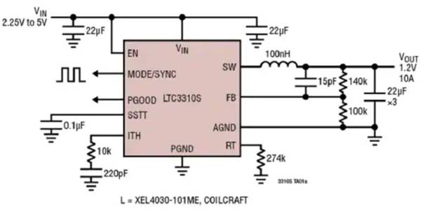
Figure 1: LTC3310 series regulator circuit schematic (Image source: ADI)
Without further ado, with ADI’s DC3042A demo board, we can evaluate the specific performance of the LTC3310 10A low-voltage synchronous buck regulator from the performance of the real circuit.
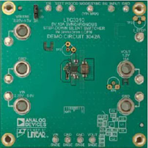
Figure 2: DC3042A Demo Board (Image source: ADI)
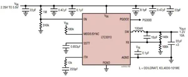
Figure 3: Schematic diagram of the DC3042A demo board (Image source: ADI)
The DC3042A demo board is set to operate in forced continuous mode with a switching frequency of 2 MHz, and can also be configured for pulse-skipping mode and a different switching frequency. Through the DC3042A demo board, engineers and friends can feel the performance advantages of LTC3310 series regulators such as ultra-low radiation, high efficiency and high-speed synchronization, and experience the fast current loop based on Silent Switcher technology.
ADI’s Silent Switcher technology has outstanding advantages in high efficiency and EMI limitation, it can provide 95% high efficiency at high switching frequency greater than 2MHz, and can help system solutions easily exceed the requirements of CISPR 25 Class 5 peak EMI limitation .
When the DC3042A demo board is running, the performance of the LTC3310 series regulators in terms of efficiency and load current can be seen in Figure 4, where the blue line is the forced continuous mode and the red line is the pulse skipping mode.
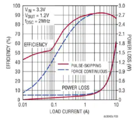
Figure 4: LTC3310 regulator efficiency and load current performance (Image source: ADI)
Figure 5 shows the capability of the LTC3310 family of regulators in terms of load step response, and Figure 6 shows the results of the LTC3310 family of regulators in a CISPR25 Class 5 peak limit test.
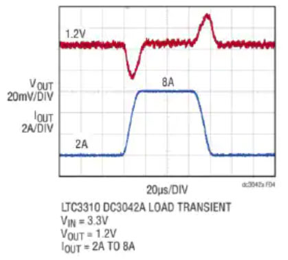
Figure 5: LTC3310 regulator load step response (Image source: ADI)
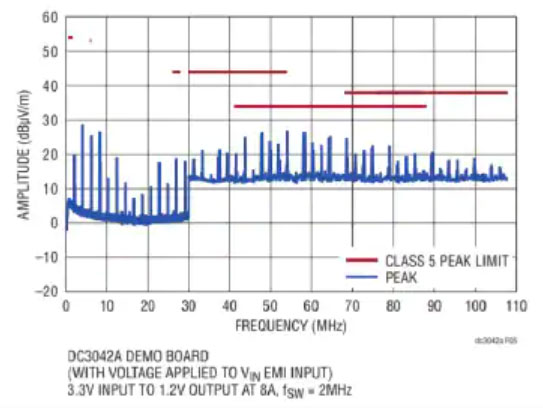
Figure 6: CISPR25 Class 5 Peak Limit Test (Image Source: ADI)
In addition, the DC3042A demo board is equipped with an EMI filter, which can reduce conducted EMI, supplemented by the ultra-low radiation characteristics of the LTC3310 series voltage regulator, which reduces the EMI/EMC radiation to a low point, which is a good reference value in circuit design. .
The Voltage Comparator and Its Multifaceted Applications
Next, we use the voltage comparator as an example to illustrate the importance of development tools for understanding the device. The pin structure and circuit symbol of the voltage comparator are similar to those of the operational amplifier. The voltage at the input terminal is used as a reference value, and the other is used as a comparison value to output a high level or a low level. The principle is very easy to understand, but simple transformation circuits can play different roles, such as overvoltage comparators, zero-crossing voltage comparators, window comparators, and hysteretic comparators.
For example, the BM1Z101FJ voltage comparator from the manufacturer ROHM semiconductor sold by Mouser Electronics is a zero-crossing voltage comparator that can output the AC voltage zero-crossing timing detection and the diode rectified DC voltage. The BM1Z101FJ is a 600V high-voltage monitor. Compared with the traditional zero-crossing detection circuit, the BM1Z101FJ does not require an optocoupler and external components, which can greatly reduce the number of components and achieve near-zero (0.01W) standby power consumption.
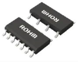
Figure 7: BM1Z101FJ voltage comparator (Image source: ROHM Semiconductor)
For home appliance applications such as rice cookers and dryers, and home appliances equipped with motors such as air conditioners, washing machines, and vacuum cleaners, the voltage clamping function integrated in the BM1Z101FJ can protect the downstream MCU and ensure that the MCU input does not exceed 4.8V. Even with different supply voltages (100V to 230V) and different MCUs used in different countries, the motors can be driven efficiently.
If engineers and friends need to purchase this device and want to know more about the excellent performance of this device in AC voltage zero-crossing detection, they can experience it through the Roma Semiconductor BM1ZxxxFJ evaluation board. The manufacturer number on the Mouser Electronics website is BM1Z002FJ -EVK-002.
As shown in Figure 8, ROHM has built three evaluation boards for the BM1ZxxxFJ series of voltage comparators. The BM1Z002FJ-EVK-002 we selected this time is the only isolated AC (alternating current) zero-crossing detection circuit.
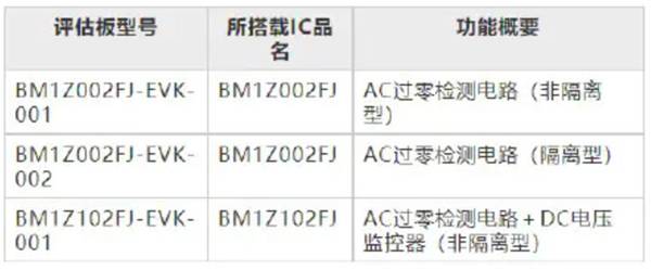
Figure 8: BM1ZxxxFJ evaluation board types (Image source: ROHM Semiconductor)
Through the BM1ZxxxFJ evaluation board, you can intuitively feel the advantages of a series of BM1ZxxxFJ voltage comparators including BM1Z101FJ compared to traditional zero-crossing detection circuits. As shown in Figure 9, the BM1ZxxxFJ voltage comparators are able to see exactly when the input AC voltage from 90 VAC to 264 VAC has zero voltage crossings.
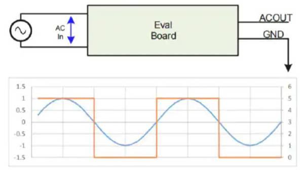
Figure 9: Zero voltage crossing (Image source: ROHM Semiconductor)
In the actual test process, when the load stops, the BM1ZxxxFJ evaluation board can stop the voltage just at 0V, as shown in Figure 10. This precise pulse control improves the safety of the circuit. Obviously, these cannot be deciphered by parameter reading.

Figure 10: Zero state capture (Image source: ROHM Semiconductor)
In addition, through the BM1ZxxxFJ evaluation board, we can also clearly see the advantages of the BM1ZxxxFJ series of voltage comparators in terms of miniaturization, eliminating the need for optocouplers and external components required in traditional ZCD circuits.
Development tools give you a better understanding of power management devices
The ADI DC3042A demo board and ROHM Semiconductor BM1ZxxxFJ evaluation board examples illustrate the importance of development tools in evaluating the performance of power management devices. Through development tools, engineers and friends can intuitively feel the performance advantages that many component parameters cannot reflect, which is extremely important for purchasing power management devices and helps to quickly create efficient and energy-saving system solutions.
Of course, there are a wide variety of power management devices, and there are also a large number of development tools from TI, ADI, Maxim, ROHM Semiconductor, Infineon and other manufacturers on the Mouser Electronics website to help engineers and friends quickly and efficiently understand pre-purchased power management devices. .
The Links: CM10MD-24H BSM100GD60DLC

0 Comments for “How to quickly understand the performance of pre-purchased power devices?”