“Using the finite element method, with the help of the computer software solidwork to carry out 3D modeling of the connector, carry out the finite element model analysis of the 3D model of the connector component, carry out the stress and strain analysis of the yield force calculation and the material, and provide mechanics for the connector design Theoretical basis.
“
Using the finite element method, with the help of the computer software solidwork to carry out 3D modeling of the connector, carry out the finite element model analysis of the 3D model of the connector component, carry out the stress and strain analysis of the yield force calculation and the material, and provide mechanics for the connector design Theoretical basis.
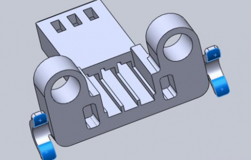
The structure of the connector: including the connecting wire fixing block ①, the connector female end ②, the connecting wire ③, the connecting metal terminal ④, the connecting metal terminal ④ and the connecting wire ③ After riveting, it is fixed to the connector female end ②, the connecting wire ③The tail is fixed with the fixed block ① by injection molding, and the arc surface of the female end ② of the connector is tightly connected with the product. Because this is commonly used in electrical appliance design, it is selected as the object of research and analysis.
The connector encountered the following problems in the production injection molding process: 1. The arc size of the connector female end ② tail is more difficult to control; 2. The arc part of the connector female end will break when the test force reaches 150N. 3. The injection molding process The mid-curved surface has a tendency to deform by 0.1mm after being calculated by the moldflow structure. Design and improve the problems encountered in the production process. In view of the deformation of the connector female end and the too small mounting surface, we redesigned the plastic bracket that the connector matched to solve the problem of the arc part of the connector completely matching the bracket. .
Save the connector 3D model in Solidwork as a file named with the .stp suffix, and choose to import it in the same format during the operation of the Patran program. Because the connector model designed in Solidwork in mm units, it must be imported in the connector It is specified that the unit of mm is used as the design length requirement. Before importing, enter the Geometry Scale Factor in the preference menu and set 1000.0 (millimeter) as the length unit, and select and select the file format with the suffix .stp to import.
Since the force received by the connector is the top end, that is, when the arc-shaped part of the connector has the largest axial load, the load received is a static load. According to the product structure and assembly requirements, the arc part of the connector is fixed and the top is stressed. The shell material is PA66, the terminal is C5191, the elastic modulus of C5191 material is E=2.62Gpa, Poisson’s ratio v=0.34, and the yield strength σb (MPa): ≥69.
In the finite element mesh division and material definition, this paper uses solid elements in the finite element analysis. Taking into account the complex shape of the back boss of the connecting terminal and the Solidwork import in the solid format, the mesh cannot be divided by ISOmesh. This article uses mesh. The format of /solid/Tetmesh/tet4. According to the design function requirements, the boss plane on the top of the connector is used to constrain the space force. According to the design requirements, a force of no less than 100N should be applied to the connector and the load is applied to the top.
The connection terminal material is PA66, the elastic modulus E=2.62Gpa, and the Poisson’s ratio v=0.34. Since only static analysis is performed, other properties of the material are not substituted into the calculation analysis. Enter the property value of the material in Materials, and then select the established material property for the finite element model in properties to complete the definition of the connecting shell material and the properties of the analysis element.
According to the analysis of statics theory, the bending moment of the connector near the arc is the largest, which belongs to the dangerous surface of deformation. Through the finite element analysis, the maximum stress of the connecting terminal is located on the outer side of the arc, which is in good agreement with the conclusion of the static analysis. From the finite element analysis results, it can be seen that the maximum stress of the connecting terminal is 2.7Mpa, the maximum displacement is located on the curved surface, and the maximum displacement is 0.047mm. According to the material manual, the yield limit of PA66 is 69Mpa. In the case of additional ultimate load, consider other The working strength of the connector is correspondingly reduced due to the influence of the external force load factor inserted in the assembly, and the arc part of the connector can meet the design requirements.
The Links: PM30RMC060 BSM300GB60DLC
0 Comments for “In connector design, simulation technology provides a theoretical basis for mechanics”