“Modern factories employ automated systems that rely on feedback from many sensors throughout the factory to maintain high productivity. These companies employ digital fieldbuses to aggregate the vast amounts of data collected by sensors. The more data the sensors collect, the better the system will adapt and operate.
“
Modern factories employ automated systems that rely on feedback from many sensors throughout the factory to maintain high productivity. These companies employ digital fieldbuses to aggregate the vast amounts of data collected by sensors. The more data the sensors collect, the better the system will adapt and operate.
Therefore, modern industrial sensors with fieldbus connections must detect signals at a faster and more precise rate and output this information as a digital signal as opposed to a traditional analog signal. This feature requires the sensor to use a more powerful processor. Also, since there are more of these sensors in the factory, the form factor becomes smaller. Increased power and smaller form factors have forced factories to abandon mature linear regulator solutions in favor of switching regulator solutions.
The use of switching regulators has created new challenges. The switching regulator form factor is larger due to the additional area required for the Inductor. The relationship between the switching frequency of the regulator and the frequency of the measurement signal must be considered.
Therefore, the layout of the converter is more critical. A poorly designed switching regulator will raise the noise floor and create unwanted electromagnetic compatibility (EMC) that will interfere with the detection of small signals.
Fortunately, we currently offer integrated inductor DC/DC switching regulators that can minimize these challenges. The integration of the inductor not only reduces the area of the switch node, but also makes it easier to achieve optimal layout. The significantly higher switching frequency of new DC/DC converters allows the use of small chip inductors and ceramic capacitors, making DC/DC converters the smallest form factor option.
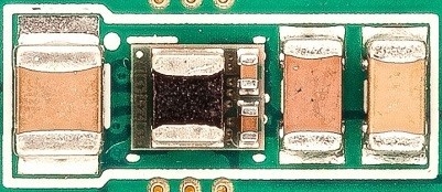
The new LMZM23601 power module integrates DC/DC converters, inductors, Vcc filter capacitors and boost capacitors into a 3mm*3.8mm*1.6mm package. This can handle input voltages up to 36V and step down from 15V to 2.5V (fixed 5V and 3.3V optional) while outputting currents up to 1A. As shown in Figure 1, a complete 1A solution is achieved with minimal on-board space.

Figure 1: LMZM23601 solution for 3.3V to 5V output, up to 1A
Compare the LMZM23601 with a traditional linear regulator solution to meet the following requirements for field transmitter applications:
Input voltage: 10V to 30V, nominal 24V
Output voltage: 3.3V
Output current: 35mA
Temperature range: ambient temperature -40°C to 85°C
Board area: 4mm*4.5mm
As shown in Table 1, the LMZM23601 offers advantages in package area and thermal energy compared to the Micro Small Outline Package (MSOP)8. Note: RӨJA specified in Table 1 is for comparison reference only, in practical sensor applications, this value will be higher due to limited board space and copper busses. The Joint Electronic Device Engineering Council (JEDEC) or Evaluation Module (EVM) calculates typical RӨJA values from datasheets. For example, the RӨJA of LMZM23601 45°C/W is calculated based on a 30mm*30mm double-layer circuit board.
|
Design options |
Package size (mm) |
Package area (mm2) |
package thermal energy RӨJA (ᵒC/W) |
|
LMZM23601 |
3 x 3.8 |
11.4 |
45 |
|
Linear CMSOP-8 |
5×3 |
15.0 |
60 |
|
Linear-Heat Sink Thin Small Outline Package (HTSSOP) |
5.1 x 6.6 |
33.7 |
39.7 |
|
Linear – Transistor Outline (TO) – 252 |
10.7 x 15.9 |
169.4 |
26.9 |
|
Linear CTO-263 |
10.4 x 6.7 |
69.7 |
24.7 |
TABLE 1: LMZM23601 AND LINEAR REGULATOR DESIGN OPTIONS BY PACKAGE TYPE
As shown in Table 2, the power consumption of the linear regulator is (24V-3.3V) x 35mA, which is approximately equal to 0.93W of power, while the power consumption of the LMZM23601 is only 0.116W. The temperature rise of the MSOP-8 packaged linear regulator makes the junction temperature higher than the standard integrated circuit (IC) junction temperature of 125°C, while the junction temperature of the LMZM23601 is 90°C according to the 45°C/W RӨJA. Even multiplying RӨJA by a factor of 5 yields a maximum Tj below this junction temperature.
|
Design options |
Power consumption (W) |
temperature rise (°C) |
Junction temperature (°C) |
|
LMZM23601 |
0.1155 |
5.2 |
90 |
|
Linear CMSOP-8 |
0.9355 |
56.13 |
141 |
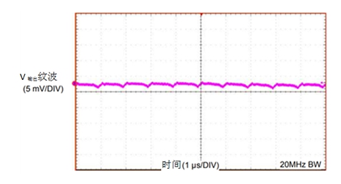
From this example, it is clear that a linear regulator is not a viable solution from a thermal point of view. The trade-off with switching schemes (even with modules like the LMZM23601) means that output ripple must be considered. As shown in Figure 2, the peak-to-peak output ripple of the standard LMZM23601 design at 3.3V is about 3mV.Table 2: Thermal Considerations for 24V to 3.3V Conversion at 35mA

Figure 2: Output ripple of LMZM23601EVM at 3.3V output
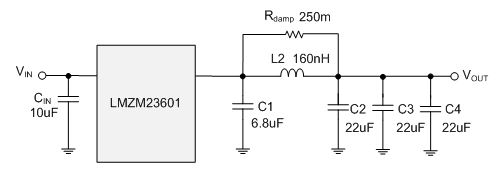
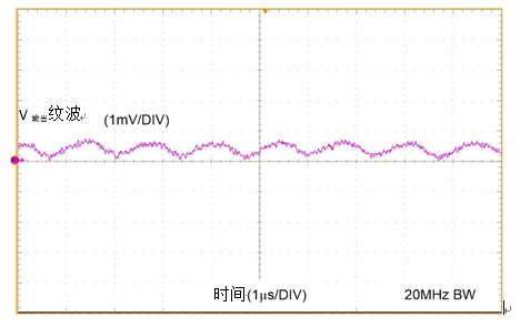
To further reduce the output ripple, a secondary filter can be used, as shown in Figure 3. Figure 4 shows that the peak-to-peak output ripple has dropped from 3mV to less than 1mV.

Figure 3: LMZM23601 with secondary filter

Figure 4: LMZM23601 output voltage ripple with secondary filter
Switching regulators are the only viable option for industrial sensors that meet compact board space requirements. The LMZM23601 integrated inductor not only provides high performance in a smaller solution size than a linear regulator, but also has the efficiency of a switching regulator.
The Links: LM190E08-TLGE https://www.slw-ele.com/ltm220m3-l02.html“> LTM220M3-L02

0 Comments for “Is it really good to use a switching regulator for the power supply of industrial sensors?”