[Guide]This article describes how a special converter equipped with PassThru™ (pass-through) mode works when the input voltage of the circuit is too high or too low to supply power to the load. This article will use examples to illustrate how to use buck-boost regulators and boost regulators equipped with a pass-through mode to increase power supply efficiency and improve EMC performance.
In some applications, the existing power supply voltage can directly drive the load without using an additional voltage converter. Sometimes, when the operating state is abnormal, the power supply voltage may be too high or too low to directly supply power to the load. In these cases, special voltage converters optimized for this operation can be used. For example, an industrial 24 V system is such an application. We assume that the load requires a 24 V supply voltage, but the usable 24 V input voltage sometimes increases to 38 V or decreases to 15 V, which exceeds the allowable supply voltage range of the load. For these applications, a typical boost regulator or a buck-boost regulator can be used.
Figure 1 shows a system diagram for this type of application. Portable radio equipment is powered by batteries. The load can accept voltages between 10 V and 14 V, but the output range of the voltage source may be 8 V to 16 V. Then the interpolated buck-boost regulator can convert the voltage to 12 V at the output. If the power supply voltage is slightly lower than 12 V, the converter will work in boost mode, and if the power supply voltage is higher than 12 V, it will work in step-down mode.

Figure 1. The allowable voltage range of the load in the system is smaller than the possible voltage range of the power supply.
Use pass-through mode to achieve improvements
A system such as the one shown in Figure 1 works well, but there is still room for improvement. If the voltage of the voltage source can directly supply power to the load most of the time, then a buck-boost regulator can be used in direct mode. At this time, within the input voltage range defined by the power supply designer, the input voltage will be directly transmitted to the output of the buck-boost regulator. The advantage of this operation is that it does not produce any form of switching loss, and the circuit efficiency is very high. In addition, since no current pulses are generated in this mode of operation, the amount of electromagnetic radiation generated during circuit operation is extremely low.
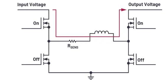
Figure 2 shows the power stage of the new LT8210 buck-boost controller circuit with pass-through mode. In this mode, the two high-side switches of the H-bridge are permanently turned on, and the two low-side switches are permanently turned off. In this way, depending on the current and voltage conditions, nearly 100% efficiency can be achieved.

Figure 2. The LT8210 buck-boost regulator with pass-through mode is used to deliver voltage in standard operation.
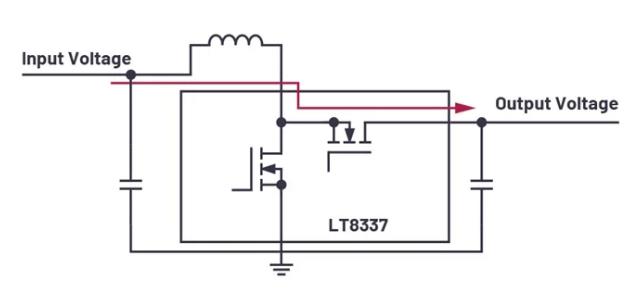
In addition to the buck-boost solution (LT8210), the boost regulator also supports pass-through mode. ADI’s new LT8337 Silent Switcher® boost regulator itself integrates a direct mode. Figure 3 shows this concept behind the LT8337 boost converter. When the pass-through mode is enabled, the high-end switch is permanently on and the low-end switch is permanently off.

Figure 3. The LT8337 boost regulator using Silent Switcher technology also provides a direct mode.
In a boost regulator, the high-side switching is usually performed by a flyback diode. In this way, the power supply voltage of the regulator that increases above the set output voltage will automatically pass through the Inductor and flyback diode. However, the dedicated pass-through mode can help effectively reduce the voltage drop of the diode by actively turning on the high-side MOSFET. The pass-through mode is also responsible for turning off all unnecessary functions of the LT8337. Therefore, the current consumption of the IC itself may only reach 15 µA. This is particularly effective for battery-powered applications.
summary
The pass-through mode can increase the efficiency of the power supply and improve the EMC performance. For applications where the available power supply voltage is usually within the allowable voltage range of the load, these advantages are particularly effective. However, the user must also be aware that in the pass-through mode, output voltage regulation will not occur within the defined voltage threshold range, although this regulation is not required in many applications.
(Source: Analog Devices)
The Links: LM64P101 PM100RSE120

0 Comments for “The input voltage is too high/low to supply power to the load? Special converters can work!”