Generative Design (Generative Design) is a process of designing by writing algorithms and programs. It is a process of human-computer interaction and self-innovation. Specifically, the designer chooses the strategy of generating the model, writes the algorithm, and uses human-computer interaction. Parametric modeling, according to objective design goals, combined with simulation and optimization methods, until the optimal design is obtained.
Generative design can create design schemes that are not easily obtained by manual modeling. They have complex geometric structures. One of the advantages of additive manufacturing technology in industrial manufacturing is to manufacture complex structures. It can be said that generative design is different from Additive manufacturing technology is a natural “good partner”, and generative design will further release the application potential of additive manufacturing. In this issue, we will continue to show the unique charm of generative design through typical cases of generative design.
![]() Define the generative model of geometric spatial relations
Define the generative model of geometric spatial relations
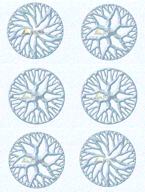
We can determine the model generation rules by defining geometric relations. Take the design of spokes as an example, if you define a geometric relationship: the spokes are a group of branch structures, the branch nodes are located on a series of concentric circles, the layers can be twisted, the number of groups, the number of branch layers, the torsion angle, the radius of the concentric circles They are variable parameters within a certain range. So when we change any parameter, different results will be generated. Assuming that the number of groups can take 10 values, the number of layers can take 4 values, the torsion angle can take 20 values, the concentric circle radius combination can take 50, and the torsion range can take 10 combinations, then 400,000 results will be generated. Here we only show dozens of them, as shown in Figure 1.
Figure 1 Generative design of spokes.Source: Anshi Asia Pacific
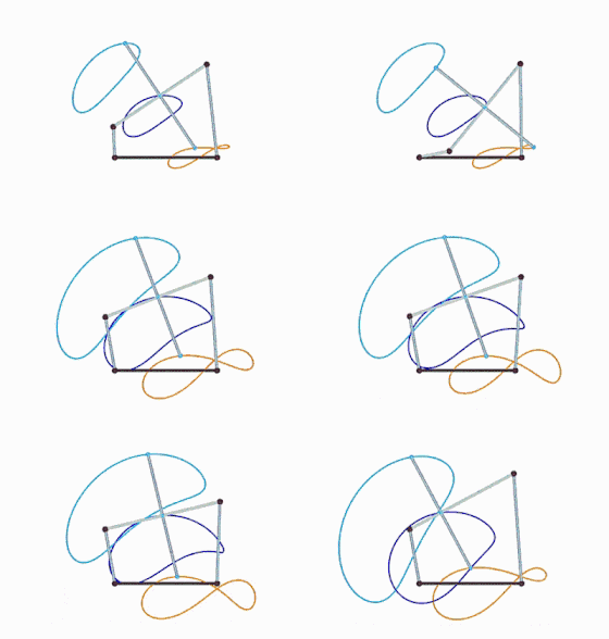
The geometric spatial relationship can also define the relationship between the various parts of the mechanism, the spatial layout of the various parts of the product, and so on. For example: the most commonly used crank-rocker mechanism, as shown in Figure 2, is composed of four rigid rods hinged. Among them, the frame is fixed, the crank is usually driven by a motor to rotate, and the follower rocker is fixed and hinged around it. The point swings, the connecting rod moves in a plane, and different points on the connecting rod have their own specific movement trajectories, which are called connecting rod curves.
Figure 2 The crank-rocker mechanism of the four-bar linkage.Source: Anshi Asia Pacific
When it is satisfied that the sum of the shortest rod and the longest rod is less than or equal to the sum of the lengths of the other two rods, and the shortest rod is adjacent to the frame, the shortest rod is a crank. If the sum of the length of the shortest rod and the longest rod in the hinged four-bar mechanism is greater than the sum of the lengths of the other two rods, there is no crank. Through the generative design program to define the connection relationship and size relationship between the components, give the crank a rotation, the mechanism will move according to the constraint relationship, determine a certain point on the connecting rod, and then determine the connecting rod curve at that point. If you change the size of any rod, or change the point on the connecting rod, you can intuitively see that the connecting rod curve changes accordingly.
![]() Define the shape and change the rules to generate the model
Define the shape and change the rules to generate the model
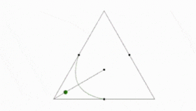
The shape change can be controlled by the parameter change. If the design is clever, one parameter can generate complex changes. Take Figure 3 as an example. In an equilateral triangle, we take a vertex and the midpoint of the two adjacent sides. The vertex and the center of the triangle are connected to a straight line. Three points composed of points generate a NURBS curve. We can use a parameter to determine the position of the point on the straight line. When the parameter is changed, the point moves, and the NURBS curve changes accordingly. We extend this change to the entire triangle, observe the graph change of the NURBS curve with the parameter, and then expand to multiple triangle arrays, observe the graph change with the parameter.
Now, if we associate this parameter with the X coordinate of the position of the triangle center point, take the X coordinate value as the independent variable, and use the dependent variable obtained by a mathematical equation as the parameter to control the position of the moving point in the graphic array. , It will produce wonderful changes.
Figure 3 An example of parameter control deformation (refer to Shape3D’s case).Source: Anshi Asia Pacific
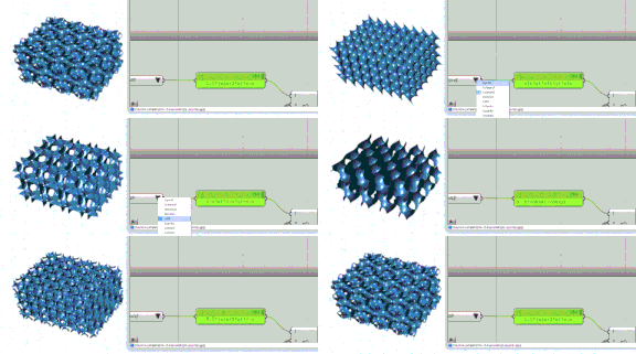
The shape change can also be controlled by a certain mathematical relationship. A very typical example is that the generation of minimal surfaces is completely defined by mathematical equations, as shown in Figure 4.
Figure 4 The mathematical relationship defines the shape.Source: Anshi Asia Pacific
The model can also be generated by a certain shape change rule. The shape change rule can use some existing program modules, or you can program it according to your own ideas. A very interesting deformation rule, as shown in Figure 5, this deformation rule is like a child’s appearance is the result of the combination of parents’ genetics.[1]
Figure 5 An example of using the shape change rule to generate a model.Source: Anshi Asia Pacific
![]() Design smart products that interact with the real world through data interaction
Design smart products that interact with the real world through data interaction
External data input can be used to change the shape, drive mechanism model movement, and output data to drive real machine movement. External data can come from hardware, software, documents, etc. Hardware data, such as real-time sensor data, PCB board transmission data, mouse and other interactive device data; software data, such as output data of other programs, collected point cloud data, etc.; document data, including: excel data, pictures, SHP, PDB etc. These capabilities allow us to do many things, such as interactive dynamic models, customized designs, digital prototypes, digital twins, and so on.
The following are some examples of the application of generative design in interactive intelligent design.
Figure 6 is the use of Grasserhopper, Firefly and Kinect by ArtyomimMaxim to track user gestures and drive EURITELED lamps to move with Arduino and MAX485DMX transceivers.[2]
Figure 6: Gesture tracking controls LED rotation.Source: Anshi Asia Pacific
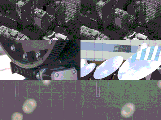
The device in Figure 7 is three computer-controlled mirrors installed on the roof of a building in the center of Santiago (Chile). They reflect sunlight onto a nearby large facade, draw oval patterns throughout the day, and control the software for the mirrors. It was developed using GH. GH simulation is where all geometry and ray tracing take place. It can precisely control and calibrate the mirror. It obtains Cartesian coordinates from the position of the light spot on the facade, polar coordinates from the position of the sun in space, and outputs a serial string with appropriate motor coordinates. These instructions are sent to the engine of the machine every second by the Arduino interface, so that the light spot projected by each mirror converges at a point behind its orbit every hour.[3]
Figure 7 Ray tracing device.Source: Anshi Asia Pacific
The power pavilion shown in Figure 8 is the result of several months of research by Elise Elsacker and Yannick Bontinckx. Part of the research on digital manufacturing. The installation advocates the concept of “intelligent building”, which is a delicate, lightweight structure that can respond to weather conditions, human movement, or human behavior and interaction. The goal assigned to the building structure is to “redefine three-dimensional space by relying on digital data.”[4]
Figure 8 Elsacker and Bontinckx created a conceptual scale model of the Kinetic Pavilion
Source: Anshi Asia Pacific
The dynamic exterior wall of the MegaFaces Pavilion shown in Figure 9 was conceived by London architect Asif Khan and designed by iart for the 2014 Sochi Winter Olympics and Paralympics. It measures 18 x 8 meters and consists of 11,000 telescopic tubes, the so-called actuators. The actuators can be individually controlled and carry a translucent sphere containing RGB-LEDs on the top. Each actuator acts as a pixel in the entire facade and can extend up to two meters as part of a three-dimensional shape, or it can change color as part of an image or video displayed at the same time.
The dynamic exterior wall of MegaFaces Pavilion is capable of reproducing 3D human faces, and it shows huge 3D selfies to visitors of the building and sports fans from all over Russia. The scaling and positioning algorithm developed by Scott Eaton can take into account the light ratio, rotation, shape and other colors of the face in real time, and transform the face in real time. Then, the processed facial model is inserted into the timeline through iart’s electronic scheduling system. Finally, the image is converted into control data and sent to each actuator. The external system displays the names of the participants on the screens in front of the pavilion and sends them text messages to notify them of when their faces appeared.[5]
Figure 9 Dynamic exterior wall.Source: Anshi Asia Pacific
1. Physical simulation form-finding
Force can shape shape. The various magical shapes and dynamics of natural substances are all related to the actions of various forces and fields. This gives us inspiration that we can generate the desired shape by applying force and field reasonably like nature.
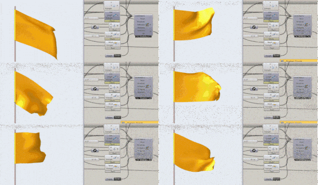
To give a simple example, the forces on a flag as shown in Figure 10 include: the binding force of the flagpole, the tensile strength of the flag material, the bending resistance, gravity, and wind power. According to the magnitude of the various forces, the flag is determined to fly Dynamic. We can take out the shape at any time as our design shape.[6]
Figure 10 Flag in the wind.Source: Anshi Asia Pacific
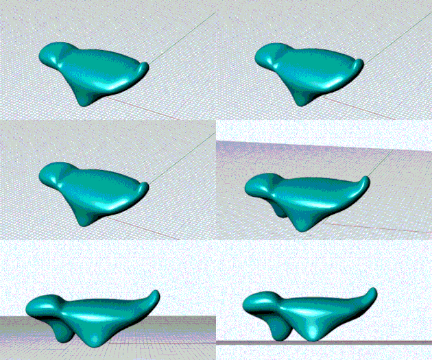
Let’s look at an example of finding a balanced posture through force, as shown in Figure 11.[7]
Figure 11 balance_solid.Source: Anshi Asia Pacific
2. Bionic growth
The bionic design of the generative design method is not simply imitating the shape of living beings, but by finding out the law of biological growth, and abstracting the external factors such as the environment into a certain range of changing parameters, and then compiling the algorithm based on the law, and then generating it through the algorithm Model process.
As shown in Figure 12, the modeling is inspired by the branching form of plants and algae, through simulating growth to create an organic model, in which individuals expand and branch, compete for resources in the environment and repel each other to fill the space.[8]
Figure 12 An example of a bionic growth algorithm.Source: Anshi Asia Pacific
3. Design-simulation integration
The example in Figure 13 uses a script that superimposes two waves around any given surface. The designer can increase the depth and stiffness of the initial geometric structure through the waveform function to generate a ridge structure. By controlling the amplitude, frequency and phase of the wave, the designer can Use several parameters to explore a large design space (the collection of all generated results). Because the interval of these parameters can be small, the design space contains countless results. At this time, find the ridge structure with the highest stiffness , Must rely on simulation and optimization tools. In this example, the design, simulation, and optimization are integrated. The genetic algorithm obtains the corresponding ridge structure by changing the parameters, and calculates the deformation of the structure through the simulation calculation program. This process is repeated and iterated automatically, and finally the minimum deformation is obtained. The ridge structure.[9]
Figure 13 Waveform ridge structure design-simulation-optimization integration.Source: Anshi Asia Pacific
Due to the time relationship, this case did not include the generation and topology optimization of the lattice structure. In fact, the generative design method may be the most suitable for the generation of the lattice structure. For topology optimization, it is convenient to set the conditions and constraints, and the subsequent smoothing process. The above only shows a few rule cases, far from covering the space and shape grammar rules of generative design for exploring innovative design. As shown in the generative design process in the previous conceptual part, generative design is a design process based on systems engineering. It needs to clarify their relationships around tasks, design goals, functions, constraints, geometric relationships, deformation rules, etc., Many of the rules are formulated to reflect the designer’s design ideas.
Reference materials:
[1]From pufferfishexamples
[2] http://www.fireflyexperiments.com/gallery-p1
[3] http://www.fireflyexperiments.com/gallery-p1
[4] http://designplaygrounds.com/deviants/kinetic-pavillion/
[5]https://iart.ch/en/-/die-kinetische-fassade-des-megafaces-pavillons-olympische-winterspiele-2014-in-sotschi
[6]From Kangaroo-examples
[7]From Kangaroo-examples
[8]From Nervous system
[9]From Millipede-examples
Zhang Xiaojun
Master of Engineering in Mechatronic Engineering, Registered Mechanical Design Engineer of Chinese Mechanical Engineering Society, Senior Engineer. He is currently an advanced design and manufacturing senior technical expert and innovation consulting expert of Anshi Asia-Pacific Company.
He has 14 years of working experience as a teacher, 10 years of experience in enterprise product research and development, and 9 years of research experience in innovation consulting and design methods. The first inventor of multiple patents, and multiple patents obtained have been successfully applied to products; among them, CN102141507A increased the pass rate of key indicators of the product from less than 10% to more than 95%, and realized fully automatic Adjustment, and did not increase the cost.
(Editor in charge: admin)








0 Comments for “13 moving pictures to see typical applications of generative design”