
In 2019, GE Aviation celebrated its centenary with strong performance.The total number of undelivered orders at the end of the year reached 270 billion U.S. dollars, And the total installed capacity of more than 64,000 commercial and military engines. These engines will be in service for several decades, which will continue to bring predictable income. GE’s team is constantly introducing advanced technologies to the commercial and military engine markets to expand market share. GE will3D printingThe innovation applied to the engine is constantly improving to achieve better performance of the engine, thus driving the creation and development of added value in the entire aviation industry.
 GE Chairman and CEO Larry Culp at the GE Aviation Parts Service Center. Source: GE
![]() Innovation comes from a strong corporate vision
Innovation comes from a strong corporate vision
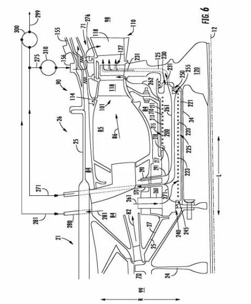
Recently, according to GE’s approved patent US10605168B2, GE’s innovative system design allows for a higher bypass ratio compared to other gas turbine engines with similar power output compared to existing gas turbine engine configurations (such as turbofans). And the total pressure ratio. GE’s innovative system increases the overall gas turbine engine efficiency by improving the bypass ratio and total pressure ratio.
 Source: US10605168B2
The high-pressure turbine includes nozzle guide vanes between the combustion part and the high-pressure turbine rotor. The nozzle guide vanes are used to accelerate the flow of combustion gas leaving the combustion part to more closely match or exceed the high-pressure turbine rotor speed along the tangential or circumferential direction.
The turbine section of a conventional gas turbine engine usually includes continuous fixed and rotating airfoils or blades and blades, respectively. This conventional configuration generally restricts the flow of combustion gases entering and exiting the blades and each stage of the blades. However, conventional turbine parts, especially fixed airfoils (ie, blades and nozzle guide vanes) require large and large amounts of cooling air to avoid the risk of damage due to hot combustion gases.
Generally, the nozzle guide vanes are designed to withstand the highest combustion gas temperature (ie, hot spot) along the annulus, which can be significantly greater than the average combustion gas temperature along the annulus. Thus, the conventional engine is designed to use a large amount of cooling air from the compressor section to reduce the possibility of structural damage, wear, deterioration, and eventual maintenance and repair of the nozzle guide vanes. However, this cooling air adversely affects overall engine efficiency, performance, fuel consumption, and operability, which could have been used in combustion to drive turbines, compressors, and fans.
When it is determined that a gas turbine engine needs to enter a maintenance and repair interval, the nozzle guide vanes are usually the limiting component, thereby limiting the overall engine performance and efficiency.
A known solution to increase the efficiency of the turbine section is a solution in which the rotors of the turbine section cross each other. For example, a turbine section is arranged in series flow from the upstream end to the downstream end in the longitudinal direction. The turbine section has nozzle guide vanes, a high-pressure turbine rotor, another turbine blade stage (that is, a fixed airfoil), and interleaved with the low-pressure turbine. Medium pressure turbines. Another known solution is to configure the turbine section in a series flow manner, the turbine section having nozzle guide vanes, a high-pressure turbine rotor, and thereafter interdigitated rotors of various levels, including low-pressure, medium-pressure, or high-pressure turbine rotors.
Although there are various known solutions, there is still a need to design a structure that enables the turbine section to further cross each other toward the combustion section. This requires the arrangement and operation of turbine section bearings to effectively use compressed air for bearing operation and engine cooling.
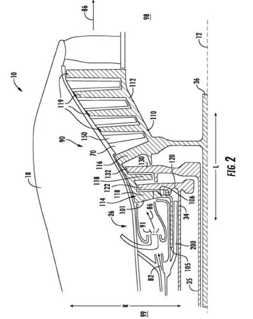 Including inner cover 112, outer cover 114, connecting airfoil 116, multiple outer cover airfoil 118, suitable for additive manufacturing-3D printing. Source: US10605168B2
GE’s innovative system designEliminates the need for first turbine blades or nozzle guide vanes, The combustion gas may only temporarily suffer the adverse effects of the combustion hot spot, instead of being substantially continuously or constantly exposed to the higher temperature in the combustion gas.
Due to reducing the adverse effects of combustion hot spots on the turbine part, GE’s design can further improve combustion stability, reduce emissions, and reduce lean blowout (LBO).
![]() 3D Science Valley Review
3D Science Valley Review
To create a highly efficient world, GE’s mission contains more ambitious goals. Communities all over the world hope to achieve more sustainable growth. With this long-term insight into local markets, deep expertise in technology and financing, and the ability to manage complex global supply chains, GE has become a firm messenger of technological innovation .
GE9X-The most fuel-efficient jet engine in GE Aviation history
On January 25, 2020 (US time), a Boeing 777X aircraft equipped with two GE9X engines took off from Penn Airport in Everett, Washington, and successfully completed its first flight. GE9X combines more than 300 engine parts into 73D printingThe components include fuel nozzles, low-pressure turbine blades and heat exchangers that accurately allow the mixture of fuel and air to enter the combustion chamber. The other is the deflector, which allows the engine to expel the dust, sand and other debris that it has sucked in, extending the service life of the engine. Such an innovative design is difficult to produce, and even GE has never used it in a commercial jet engine before.
GE Catalyst-New turboprop engine
In addition to the GE9X engine, the ATC team at the GE Additive Manufacturing Technology Center is working closely with the engineers who developed the Catalyst. This will be the first new turboprop engine designed from scratch in 30 years. They use3D printingThe technology combines hundreds of engine parts into a dozen or so large parts.
With the approval of GE3D printingThere are more and more patents in application and engine manufacturing. GE is in this3D printing+The next generation of engine manufacturing has established a new high ground, and has accumulated more confidence to move towards its vision of creating a highly efficient world. According to 3D Science Valley market research, this series of approved patents include:
Cleaner emissions! Patent for tilt burner of GE gas turbine engine
Approval date: March 24, 2020
According to the market research of 3D Science Valley, the inclined burner of gas turbine engine developed by GE can increase the flow path of the burner and the length of the premixer, while reducing the pressure loss, achieving flow uniformity, and improving the return margin to improve Performance, durability and emissions output (for example, reduced CO emissions). The whole or part of the burner assembly developed by GE can be3D printing-Additive manufacturing to achieve. Materials include high-strength steel, nickel and cobalt-based alloys or metal or ceramic-based composite materials, or other material combinations.
GE 3D printingFuel nozzle patent
Approval date: March 17, 2020
In order to achieve better functions, GE designed an ideal fuel nozzle top structure. This structure is only the size of a walnut in the end, but there are 14 delicate fluid channels inside. GE passed3D printing-Additively manufactured fuel nozzles have several advantages. It provides a method of effective cooling by split flow, and has good aerodynamic and acoustic characteristics. Analysis shows that the hollow splitter, spiral swirl blade and compound angle venturi tube are particularly advantageous when used in combination in fuel nozzles.
GE will3D printingManufacturing of liquid fuel cartridge assembly applied to gas turbine combustor
Approval date: March 3, 2020
GE adopts3D printing-Additive manufacturing technologies such as selective metal melting additive manufacturing systems based on powder beds or other additive manufacturing systems to manufacture cutting-edges.3D printingThe device helps to introduce liquid fuel into the head end of the gas turbine combustor for power generation. This device facilitates the delivery of liquid fuel (or liquid fuel/water mixture) through a centrally positioned liquid fuel cartridge.
Reference materials:
-US10605168B2
-US10598380B2
-US10591164B2
-US10578306B2
-US10415833B2
(Editor in charge: admin)
0 Comments for “GE interdigital turbine engine air bearing cooling structure and thermal management method patent passed”