
Wind power is considered to be one of the cleanest and most environmentally friendly energy sources currently available, and wind turbines have received more and more attention in this regard. Modern wind turbines usually include a tower, generator, gearbox, nacelle, and one or more rotor blades. The rotor blades capture the kinetic energy of the wind using the known airfoil principle. The rotor blades transmit kinetic energy in the form of rotational energy in order to turn the shaft that couples the rotor blades to the gearbox (or directly to the generator if the gearbox is not used). The generator then converts the mechanical energy into electrical energy, which can be deployed to the utility grid. According to the market observation of 3D Science Valley,GEpass through3D printingActively deploy technology to transform its own industry.

Better wind energy
![]() Slewing ring bearing of wind turbine
Slewing ring bearing of wind turbine
Generally, a wind turbine includes a tower, a nacelle installed on the tower, and a rotor coupled to the nacelle. The rotor generally includes a rotatable hub and a plurality of rotor blades coupled to the hub and extending outward from the hub. Each rotor blade can be spaced around the hub to facilitate rotating the rotor so that kinetic energy can be converted into usable mechanical energy, which can then be transmitted to a generator provided in the nacelle for the generation of electrical energy.
In order to correctly orient the nacelle and rotor blades with respect to the direction of the wind, wind turbines typically include one or more yaw bearings or pitch bearings. The yaw bearing allows the nacelle to rotate and is installed between the tower and the nacelle. The pitch bearing allows the rotor blades to rotate and is installed between the rotatable hub and the rotor blades.
At present, yaw bearings and pitch bearings are slewing bearings, which include an outer race and an inner race, and there are multiple ball bearings between the outer race and the inner race. In addition, a typical pitch bearing includes multiple gear teeth on the inner race, while a typical yaw bearing includes multiple gear teeth on the outer race. Therefore, one or more drive mechanisms are configured to drive the bearings by engaging gear teeth.
The inner and outer races of conventional pitch bearings and yaw bearings are manufactured through a forging process, which can be time-consuming and expensive. Therefore, GE uses additive manufacturing technology to make improvements in the yaw bearing and pitch bearing of wind turbines.
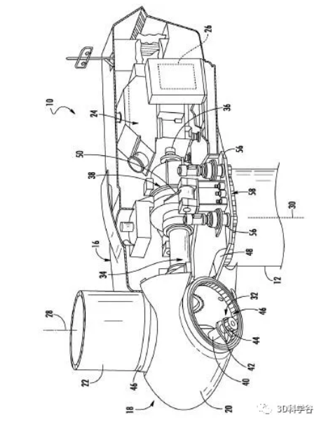 Detailed internal view of the wind turbine nacelle © GE Patent
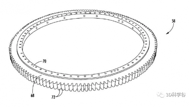 Perspective view of the yaw bearing of a wind turbine © GE Patent
According to market research conducted by 3D Science Valley, GE applies the coating material to at least a part of the gear teeth through an additive manufacturing process. The coating material is different from the base material. Additive manufacturing includes cold spraying, thermal spraying, laser cladding, adhesive spraying, material spraying, directional energy deposition, powder bed selective metal melting and other technical types. Coating materials include boron nitride, aluminum oxide, silicon carbide, tungsten carbide, nickel-based alloys, or any other material that can provide the desired hardness.
![]() Lightweight rotor blade components (such as shear webs)
Lightweight rotor blade components (such as shear webs)
A wind turbine rotor blade generally includes a suction side shell and a pressure side shell that are usually formed by a molding process, and the suction side shell and the pressure side shell are bonded together at a bonding line along the leading edge and the trailing edge of the blade. In addition, the pressure shell and the suction shell are relatively lightweight and have structural properties (e.g., stiffness, buckling resistance, and strength) that are not configured to withstand bending moments and other loads applied to the rotor blade during operation. Therefore, in order to increase the rigidity, buckling resistance, and strength of the rotor blade, one or more structural members (for example, opposed to shear webs constructed therebetween) that join the inner pressure side surface and the suction side surface of the shell half are generally used. The spar cap) to strengthen the main body shell.
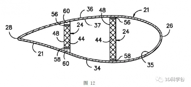 Cross-sectional view of rotor blade © GE Patent
Such structural members are usually composed of various materials, including but not limited to glass fiber laminated composites and/or carbon fiber laminated composites. More specifically, the shell of the rotor blade is generally constructed around the spar cap of the blade by stacking layers of fiber fabric in a shell mold. These layers are then usually poured together with the resin material. In addition, a similar molding process is often used to construct the shear web, and then the shear web is installed between the spar caps.
As the size of the rotor blade continues to increase, the size of the spar cap and the shear web also increases and increases the weight of the entire rotor blade. Therefore, constantly looking for new and improved structural members (such as shear webs) and their manufacturing methods have become the pursuit of manufacturers, and higher-performance structural members provide rotor blades with the required strength and rigidity, while also Minimize the total weight of the rotor blades.
According to 3D Science Valley’s market research findings, GE is exploring3D printing-Additive manufacturing, automatic fiber deposition technology and the use of CNC control and multiple degrees of freedom to deposit materials to manufacture lightweight rotor blade components with a lattice structure (such as shear webs).Which is caused by3D printingThe internal lattice structure forming the rotor blade member includes a plurality of openings.
![]() blade
blade
After making the fan taller, lighter is the next pursuit. 3D Science Valley learned that GE has established a cooperation with the US Department of Energy to study and use3D printingManufacturing fan blades.This 25-month, US$6.7 million project will focus on studying how to use low-cost thermoplastic materials and3D printingTechnology to manufacture the tip part of a set of fan blades. After completion, the GE team and its partners-Oak Ridge National Laboratory and National Renewable Energy Laboratory will test the structural characteristics of the product and install three sets of blade tips on the wind turbine.
The continuous pursuit of technological innovation has prompted GE to always seek to improve the way of blade manufacturing, including the3D printingTechnology is combined with advanced processes such as thermoforming, automation and thermoplastic materials.
At present, most fan blades are made of composite materials in which epoxy resin or polyester resin is added to glass fiber and carbon fiber, and light-weight thermoplastic composite materials and3D printingThe blade has a number of advantages, including:
-Lightweight blades can drive the fan rotor to generate more power and increase the power generation capacity of the fan
-Lightweight blades can reduce the load on the tower tube and axles, reduce the wear of gearboxes, transmission systems, bearings and bases, thereby reducing life cycle costs
-Thermoplastic materials are more convenient for melting and recycling after dismantling
After the tip part is completed, the GE team will next3D printingThe technology is applied to other parts of the wind turbine blade. More than 20 years ago, GE began to introduce lightweight composite fan blades in aero engines. Today, through the joint efforts of partners, GE is applying more advanced material technologies to wind turbine blades to reduce the cost of wind power per kilowatt-hour, improve performance, and continue to promote the green and low-carbon development of the industry.
(Editor in charge: admin)
0 Comments for “GE’s latest progress in applying 3D printing-additive manufacturing to the field of wind energy”