The fuel nozzle is an inconspicuous small part of an aircraft engine. It is like a faucet poked on two stubby brackets, which can be held with one hand. But to make this small part well, it takes one of the most disruptive technologies in GE history –3D printing-Additive manufacturing.
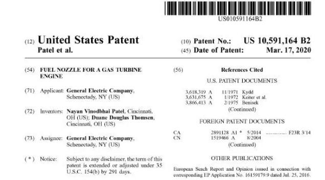
Subversion does not only come from manufacturing technology, but also from function-oriented design. Today, according to 3D Science Valley’s market observations on GE’s patents just obtained on March 17, 2020, GE has recently obtained a patent for fuel nozzles. This revolutionary product of fuel nozzles is completing its own continuous iteration. .
Source: US10591164B2
![]() Complex achievement function realization
Complex achievement function realization
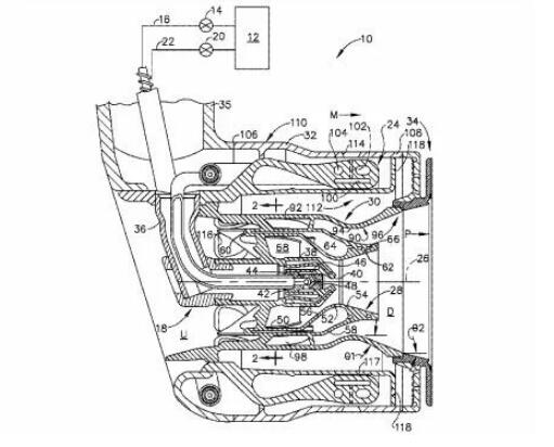
GE passed3D printingThe fuel nozzles used in gas turbine engines include the following patented designs:
Source: US10591164B2
Annular outer body: the annular outer body extends parallel to the centerline axis and has an outer surface extending between the front end and the rear end, wherein a plurality of openings pass through the outer surface;
Annular main injection ring: it is arranged on the radially inner side of the annular outer body, and the annular main injection ring includes an extended main fuel passage;
Multiple main fuel orifices: each main fuel orifice communicates with the main fuel passage and is aligned with one of the openings of the annular outer body.
Annular venturi tube: set on the radial inner side of the annular main injection ring, the annular venturi tube includes a throat with the smallest diameter, a roughly cylindrical part upstream of the throat, and a divergent part downstream of the throat;
Source: US10591164B2
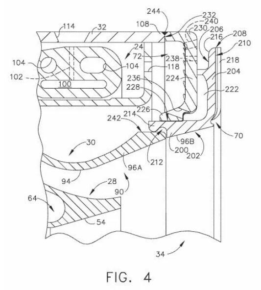
Annular separator: set on the radial inner side of the annular venturi, the annular separator includes an inner wall and an outer wall, the inner wall and the outer wall are joined together at the front end, and the inner wall and the outer wall converge toward each other to be at the rear end of the annular separator Joined together, and they are spaced apart from each other between the front end and the rear end to define a separation cavity, wherein the upstream part of the outer wall has a first contour that converges from the front end to the rear end, and the upstream part of the annular venturi The second contour, at least all the way to the throat.
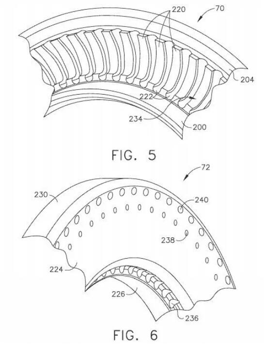
Vortex blade: a series of external vortex blades extending between the annular venturi and the annular separator, wherein the external swirling blade channel extends downstream of the external swirling blade to the outlet of the airflow from the external swirling blade, the outlet The circumferential direction between the annular venturi and the rear end of the annular diverter is defined at an axial position downstream of the throat.
Source: US10591164B2
The plurality of discharge holes communicating between the diverging cavity and the rear end of the annular diverter form an acute angle with respect to the centerline axis, so that the air discharged therefrom generates a vortex with respect to the centerline axis. And wherein the air is discharged from a plurality of discharge holes, so that the outlet of the air flow from the inner swirler blade coincides with the plane.
Compared with the existing technology, GE has adopted3D printing-Additively manufactured fuel nozzles have several advantages. It provides a method of effective cooling by split flow, and has good aerodynamic and acoustic characteristics. Analysis shows that the hollow splitter, spiral swirl blade and compound angle venturi tube are particularly advantageous when used in combination in fuel nozzles.
Review GE R&D3D printingThe road to fuel injectors is a legend in the history of aviation manufacturing. In the GE fuel nozzle head, the labyrinth of complicated runners efficiently mixes fuel and air, which can help the engine achieve superior performance. The success or failure of the LEAP project depends largely on the quality of the fuel nozzles.
In order to achieve better functions, GE designed an ideal fuel nozzle top structure. This structure is only the size of a walnut in the end, but there are 14 delicate fluid channels inside. Although this design is exquisite, it is too complicated to be made. GE tried 8 times through traditional manufacturing and processing methods, but failed each time.
Problems that traditional methods cannot solve,3D printingThe machine is like a laser pointer. According to the computer drawing, the fine metal powder is melted into the final shape layer by layer. It is suitable for the manufacture of complex and precise parts such as fuel nozzles. also,3D printingThe waste produced is also much less than traditional production methods.
Today, GE has extensive experience in manufacturing complex-shaped functional parts.3D printingTechnology has made it a reality to manufacture complex-shaped pre-mixers, GE passed3D printingThe vortex motion brought about by the premixer helps to atomize and mix liquid fuel with air, making it possible to use liquid fuel in addition to gaseous fuel. And it can produce a stable jet of flame, bringing lower dynamics and higher flame stability margin, and the high exit velocity can be used to reduce or eliminate the risk of flame flashback.
Recently, GE’s patents were approved. Not long ago, GE was also approved to3D printingA patent applied to the manufacture of liquid fuel cartridge components for gas turbine combustors. GE adopts3D printing-Additive manufacturing technologies such as selective metal melting additive manufacturing systems based on powder beds or other additive manufacturing systems to manufacture cutting-edges.3D printingThe device helps to introduce liquid fuel into the head end of the gas turbine combustor for power generation. This device facilitates the delivery of liquid fuel (or liquid fuel/water mixture) through a centrally positioned liquid fuel cartridge.
Reference materials:
-US10591164B2
-US10578306B2
-US10415833B2
(Editor in charge: admin)


0 Comments for “Heavy! GE 3D printing fuel nozzle patent passed”