Topology optimization is an optimization technique that divides a simulation domain into regions that need to be kept or removed. The optimization uses an approximate representation of the physics in the regions to be removed, so we should remove these regions from the geometry and run a new simulation to verify the optimization results. With COMSOL software, we can create geometries from topology optimization results plots for further analysis, which can be easily exported to CAD software.
This article is an excerpt from the COMSOL Blog, originally published in 2017. More information on filter datasets is included for the latest release.
![]() Use topology optimization results in your design workflow
Use topology optimization results in your design workflow
Topology optimization is a useful feature that helps us find designs that we cannot reasonably think of. However, when developing a design, this is only the first step. It may not be reasonable or possible to build a specific design found through topology optimization because the design is too expensive to produce or simply impossible to manufacture.
Topology Optimization Results for MBB Beams
To address these issues, we can propose new designs based on the results of topology optimization, and then perform further simulation analysis on them. But how do we do it? We may need a geometry that can be meshed, or an imported mesh that represents the results of topology optimization. It turns out that COMSOL allows us to easily obtain these from both 2D and 3D simulations. In COMSOL, we can use them directly or export them to various CAD software platforms. Below, we first examine how to create the geometry, and then discuss how to skip the geometry creation step and simulate directly by importing and modifying the mesh.
![]() How to Generate Geometry for Topology Optimization Results in COMSOL Multiphysics®
How to Generate Geometry for Topology Optimization Results in COMSOL Multiphysics®
In COMSOL Multiphysics version 5.5, the geometry operations used to generate topology optimization results using the Filter dataset, the steps for 2D and 3D geometry operations are the same. However, there are some additional steps to creating 2D geometry. Below, we demonstrate this process through the Minimizing Flow Rate in Microchannels case tutorial. In addition to the original tutorial, we’ll show how to import added domain and boundary selections, and how to reuse these selections when doing a validation study on newly created geometry. You can follow the link at the end of this article to download the MPH file with additional selection and validation studies to create the geometry yourself using COMSOL.
The goal of this case tutorial is to find the optimal distribution of the porous packing material to minimize the horizontal flow velocity in the center of the microchannel.
Optimized horizontal velocity (surface plot) and velocity field (streamline). The black outline represents the filler material.
In the results shown above, the black outline is the contour with the design variable equal to 0.5. It represents the boundary between the channel and the fill material, and is what we want to incorporate into the geometry. In other applications, the expressions and contour levels drawn may vary, but the principle is the same, namely finding a contour that describes the boundary between a solid and a non-solid material (usually some kind of fluid).
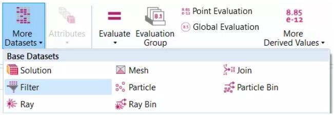
Below, we’ll use the “filters” dataset to create geometries from the results above. For 3D topology optimization studies, such datasets are automatically set up with default plots. However, for 2D topology optimization, a Filter dataset needs to be added by manually setting it in the More Datasets menu on the Results ribbon.
The More Datasets menu on the Results shelf provides a way to add filter datasets.
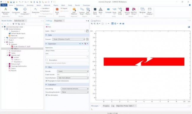
In the settings window of the “Filter” node, enter dtopo1.theta at “Expression”, and set “Lower level: 0.5. Click the “Draw” button to visualize the area represented by this level.
The settings for the Filter dataset and the domains defined by that dataset.
![]() Create mesh parts from filter datasets
Create mesh parts from filter datasets
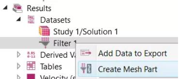
Right-click the Filters node in the Model Builder tree and choose Create Mesh Part from the menu.
Use the Create Mesh Part property as the first step in exporting created geometry from topology optimization results.
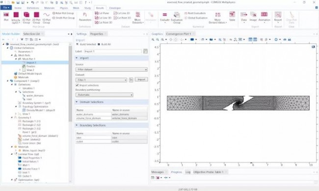
Sets the Mesh Parts based on the visualization of the Filter dataset. As shown in the image below, in the Settings window for the Mesh Parts > Import action, there is a checkbox “Import Selection”. Imported selections are also listed below Import Settings and are categorized by entity level. In this example, the selection on the original geometry is a coordinate-based selection that defines the material and physics settings for the topology optimization study.
Settings window for the import node of the mesh part. Selected settings Import Selections A selection list is listed at the bottom of the Settings window. As seen in the Model Builder tree, select the one defined under Definitions in the Geometry sequence and Component 1.
The mesh import operation supports importing any type of model selection. The most common types of selections are those added under Definition, those added in the Geometry sequence of operations, and those created during LiveLink™ synchronization and mesh import. Starting with COMSOL Multiphysics version 5.5, we can also automatically create selections based on materials, colors, objects (solids), and layers when importing CAD files.
After importing a mesh, it can be modified using operations such as Split Solids to create more solids, or Join Solids to reduce solids. Meshes can also be modified using adaptive operations before geometry is created, as shown in the Export and Import Topology Optimized Steel Hooks tutorial. For 3D meshes, we can directly export the meshes to a format compatible with COMSOL Multiphysics and CAD software, and can even be used directly for 3D printing. File formats supported for use by external software are STL, 3MF, and PLY formats, which are common file formats for 3D scanning and 3D printing.
![]() How to create geometry and reuse imported selections
How to create geometry and reuse imported selections
When the mesh meets the requirements, right-click the Mesh Parts node and select Create Geometry From Mesh from the menu, which sets up the new component in the Import node of the Model Builder geometry sequence of operations . In the article on the COMSOL website: “Improved STL and NASTRAN® File Import Functions and How to Use It”, we discuss in detail the procedures and import settings involved in 3D cases.
Imported selections can now be used to set up materials and physics in a validation study, as shown in the image below.
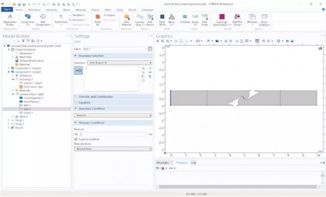 Geometry created from topology optimization results. Set the inlet boundary condition using a boundary selection imported from the mesh part.
We can also copy the MPH file, clear the geometry operation sequence, add an import operation, and point directly to the newly created mesh part. This way, just make sure the selection has been updated correctly and you can use the physics settings again.
Alternative procedure: run the validation study directly on the grid created by the filter dataset
Starting with COMSOL Multiphysics version 5.5, we use meshes created from the Filter Dataset directly without having to generate geometry. This operation adapts surface meshes to improve mesh quality, creates domains when needed and builds free tetrahedral meshes, all based on imported meshes. Begin with the tutorial exporting and importing solved results for topology optimized steel hooks, follow these steps:
Add a new 3D component and go to component 3’s mesh 4. Note that it is also possible to go to any mesh in the two existing components and choose Delete Sequence to reuse the already set up physics. In the selected component, add a mesh import action and set the source: filter dataset and dataset: filter 1 as shown in the image below. By default, the Import Selection checkbox is selected to facilitate setting up the physics for the validation study, which was discussed in the previous section. These selections are listed under Domain Selection and Boundary Selection. For this use, it is recommended to import only boundary mesh elements and create the domain mesh separately (see steps below), as this results in a better quality mesh. After importing a mesh and imported selection will be generated as shown in the image below.
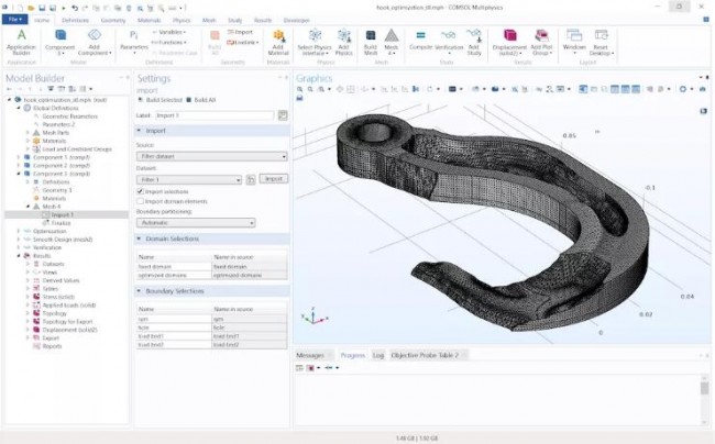 Mesh created with topology optimization results defined by the Filters dataset. The selection of the original components is transferred to the new mesh.
The mesh imported from the Filters dataset is the one used for visualization, so it is not ideal for simulation. To improve the quality of the mesh, we can add an adaptive operation with the following settings: solution: none, expression type: absolute size, size expression: meshsz/2, where meshsz is a defined parameter that defines Mesh size in topology optimization studies.
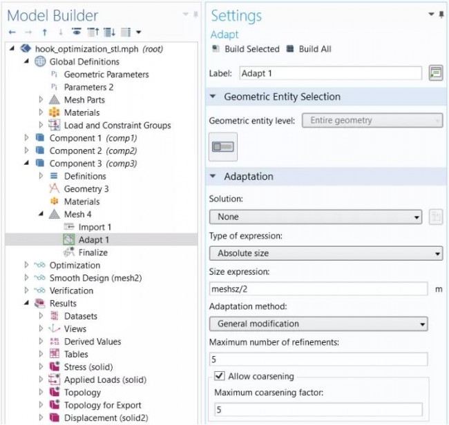 Surface mesh size adaptation expression meshsz / 2 settings
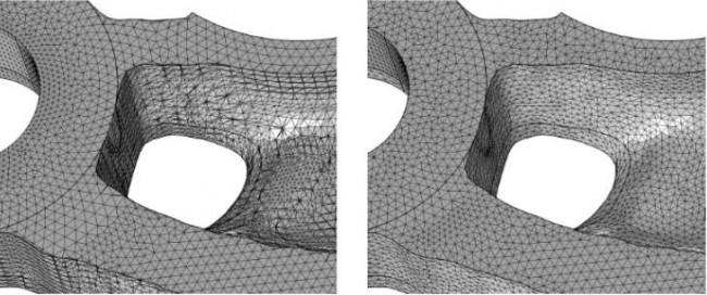 Surface meshes created before (left) and after (right) using the adaptive operation
The entity information is also transformed from the filter dataset, so even though we only transformed the face mesh, there is a domain. If importing a surface mesh from a file, you will also need to add a Create Domain action before proceeding to the next step, otherwise there will be no domains to draw the mesh. Finally, we add a free tetrahedral operation to build the domain mesh. Make sure to set the appropriate dimensions in the Size action under the Free Tetrahedron node. Here, we set the predefined mesh size to finer and build the mesh.
Now, we can set up the physics in the validation study.
We investigated the possibility to create geometries or meshes based on filter datasets. So, what do you need to consider when choosing between the two?
By creating the geometry, you can ensure that non-planar surfaces are represented by curved elements, whereas meshes created directly from the Filter dataset can only use piecewise linear representations of the boundaries. If the physics we’re solving is highly dependent on the smoothness of curved boundaries, we might want to consider creating geometry. Furthermore, by creating the geometry, we can freely re-mesh the boundary, whereas when solving the mesh created directly from the topology optimization results, we can only fit the boundary mesh.
On the other hand, creating geometry is more time-consuming and consumes more computer memory than just using a mesh. Also, depending on the shape of the topology optimization results, sometimes it may not be possible to create geometry from the results. For example, a typical case is a coarse mesh representing small or narrow regions, we may want to consider solving directly on the imported mesh.
Export 2D geometry to CAD software
The DXF format is a two-dimensional format that can be read by most CAD software platforms. DXF also describes higher-order polygons between points, so it often represents a better shape than just exporting points.
To export the optimized topology from this geometry to a DXF file, we can follow the steps below. Note that there is an optional step if you want to exclude domains in the DXF file.
- Add Union from the Boolean Operations and Splits menu on the Geometry toolbar
- Enter all objects
- Remove any unwanted fields using the “Remove Entity” function (optional)
- Click the Export button on the Geometry toolbar to import the 2D geometry in DXF format
How to export 3D drawing data in STL, PLY and 3MF formats
After performing topology optimization in 3D mode, we usually view the final shape by creating a plot of design variables, such as an isosurface plot. In COMSOL Multiphysics, STL, PLY, and 3MF files can be exported from the following plotting functions:
- body
- isosurface
- surface
- section
- faceted
- radiation pattern
If you want to export deformation graphs, the COMSOL software supports adding Deformation nodes on drawing features.
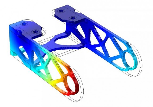 Topology optimization results of the scaffold. Colors in the volume plot represent total displacement.This drawing data can be exported directly in various formats for further use and processing in CAD software3D printing.
Exporting the data to the appropriate file format is very simple, as demonstrated in the “Brackets – Topology Optimization Example Tutorial. Right-click on the Plot Feature node and select Add Plot Data to Export. In the Plot node’s resulting Settings window , select STL Binary File (*.stl), STL Text File (*.stl), PLY Binary File (*.ply), PLY Text File (*.ply) or 3MF File (*.3mf) from the File Type drop-down list ).
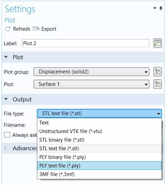 Plot data export settings. Supported output file formats for use in CAD software and 3D printing are STL, PLY and 3MF.
3MF and PLY files will also contain color data for all mesh nodes. The exported file can be easily read by most CAD software and 3D printing platforms.
If you want to compare the actual CAD drawing with the optimized results, you need to export the data in a format that can be imported into the CAD software you are using. DXF format (for 2D) and STL, 3MF and PLY format (for 3D) are widely used formats and should be able to be imported in many software platforms.
In this article, we discussed the steps required to export topology optimization results in DXF, STL, 3MF and PLY formats. This will allow us to use COMSOL Multiphysics in conjunction with CAD software to analyze model geometry more efficiently.
Article source: COMSOL
(responsible editor: admin)


0 Comments for “How to create a geometric model using topology optimization results”