Guide:3D printingTechnology, because of design freedom and simple production process, has gradually replaced traditional manufacturing.Companies are gradually introducing3D printingMachines to replace traditional, outdated production lines to manufacture discontinued parts.

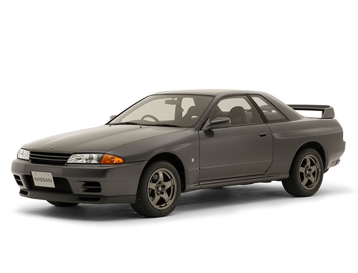
△Nissan NISMO
Antarctic Bear learned that Japan SOLIZE and US HP officially announced on March 15, 2021 that they will continue their partnership to advance digital manufacturing.At the same time, the two companies also announced that they will jointly develop and produce on-demand replacement parts for Nissan’s NISMO Heritage Part program for discontinued replacement parts, a collaboration that provides design and manufacturing for NISMO enthusiasts for the first time3D printingComponents.

△Skyline GT-R (1989: BNR32)
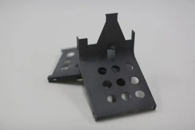
After working with Nissan to identify the best parts for 3D production, SOLIZE then partnered with HP to optimize the design and manufacture of high-quality commercial parts using the advanced capabilities provided by HP’s Multi Jet Fusion platform.Currently, the two companies will use3D printingThe first part to be repaired was the plastic part of the R32Nissan Skyline GT-R’s harness protector. This part is produced using HP HighReusability PA 11, which offers high mechanical properties and design flexibility.

△Parts produced with HP High Reusability PA 11 have high mechanical properties and design flexibility
Rebuild sustainable production supply chains
In order to facilitate maintenance and parts replacement,carManufacturers need to provide parts replacements for products over an extended period of time.Producing or storing parts for discontinued, upgraded or overhauled vehicles is challenging and expensive because manufacturers must keepmoldAnd manage inventory and logistics.digital manufacturing and3D printingBuildable virtual data inventory enables flexible design and just-in-time 3D production to meet complex part demands while reducing costs. In addition, sustainable on-demand 3D production helps reduce industrial waste and CO2 emissions throughout the product life cycle.HPcompany3D printingDigital manufacturing is a viable long-term solution for accelerating production, transforming supply chains and activating industries such as automotive, said Jon Wayne, head of global commercial practice for and digital manufacturing. The two companies will also aim to help companies transform their traditional manufacturing models through sustainable digital production methods.
About SOLIZE
SOLIZE has been a leader in digital engineering technology since the inception of 3D CAD in the 1990s, when it started using3D printingmachine for rapid template making and 3D modeling, and provide 3D CAD engineerstrainingand 3D CAD engineering services.Currently, SOLIZE provides 3D CAD/CAE engineering services for product design and analysis, MBD engineering services for model development,3D printingEngineering services, as well as sales of industrial additive manufacturing equipment and innovative engineering services for low-volume production products using additive manufacturing (metals and plastics). Transform tacit knowledge into formal knowledge to transform clients’ business and/or development processes.
HP’s Multi Jet Fusion Technology
HP Multi Jet Fusion technology builds on HP’s decades of expertise in inkjet printing, jettable materials, precision low-cost machinery, materials science and imaging.investbasically. Quickly print and cure large work areas with custom materials and innovative technologies. HPMulti Jet Fusion offers advantages in build speed and control over part and material properties, which are other3D printingcraftsmanship cannot provide. By jetting HP functional agents using HP printheads, material in the work area can be blended, detailed and transformed point by point.

△HP Multi Jet Fusion technology
1. Synchronous, scalable architecture for high productivity
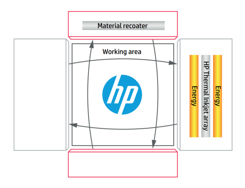
A key innovation in HP Multi Jet Fusion technology is a high-speed, simultaneous architecture that builds parts layer by layer. As shown in Figure 1, dual carriages scan the entire work area in a vertical direction: one carriage recoats the work area with fresh material, and the other carriage prints the HP functional agent and melts the printed area. This separates the recoating and printing/fixing processes so that each process can be individually optimized for performance, reliability and productivity.

△ Figure 1. Schematic diagram of HP Multi Jet Fusion synchronous printing architecture
The HP Jet Fusion 3D printingIn the machine, a section or group of parts is built layer by layer on a work area inside the HPJet Fusion 3D build cell. After the job is complete, roll the build unit into the HP JetFusion processing station to cool it down, unpack the parts, and restore and refresh the build material. After completing these processes, build units that have been updated by the HP JetFusion processing station can be rolled back into the printer for continuous production. The depth and work area of the build cell determines the size of the largest part that can be produced. HP Multi Jet Fusion technology uses scalable HP thermal inkjet technology to create print bars of different widths by stacking printheads across the full width of the scan. Because of this feature, HP can expand 2D printing solutions from PC to printer, HP can create a series of HP Jet Fusion with different sized work areas 3D printingmachine. HP printheads can also be stacked in the scan direction to increase the speed, functionality and nozzle redundancy of more nozzles for reliable print quality.
2. Print parts with HP Multi Jet Fusion technology
The printing process involves spreading a thin layer of powdered material over the entire work area. For example, in Figure 1, the material applicator carriage is scanned from top to bottom. Next, the print and fuser carriage with the HP hot-end (printhead) array and material scans the entire work area from right to left. The work area can be preheated immediately before printing to provide consistent and accurate temperature control as each layer is printed. The print head can print functional agents onto the material at precise locations to define the geometry of the part and its properties. The carriage returns from left to right to blend the area just printed.
At the end of the scan, the supply tank refills the coater with fresh paint, and the service station can test, clean and service the printheads on the print and fuser carriages as needed to ensure reliable operation. After each layer is completed, the surface of the work area retracts about the thickness of a sheet of office paper and the material applicator carriage scans in the opposite direction for optimum productivity.This process continues layer by layer until a complete part or group of parts is formed in the building unit
3. Melting and Refining Agents
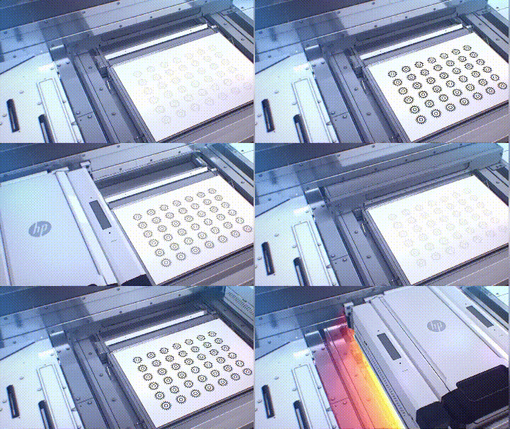
With HP Multi Jet Fusion, every layer of the part is surrounded by unfused powder. HP 3D high-recyclability printing materials are designed to minimize powder waste and can be reused in future releases. Reusability of remaining powder depends on HP3D printingmachine. For high strength and surface quality, it is important that the new layer is bonded to any previously fused material beneath it, with smooth and well-defined edges. This is accomplished through a variety of reagents applied by HP printhead arrays. FIG. 2 is a close-up view of the process described in FIG. 1 .

Figure 2. Schematic of the HP Multi Jet Fusion printing process, cutaway view
This process begins by recoating the material in thin layers over the entire work area, as shown in Figure 2a. Figures 2b-d show what happens during the first scan of the print and fuser carriages. Temperatures were measured at multiple points throughout the work area, and in Figure 2b, energy was applied to the fresh layer to control the material temperature just before the printing agent was applied. In Figure 2c, the fixer (“F”) is selectively printed, where the particles will be fused together. In Figure 2d, a refiner (“D”) is selectively printed where fusion would be reduced or amplified. In this example, the refiner reduces fusion at the boundaries, resulting in a part with sharp and smooth edges. In Figure 2e, the material is exposed to melting energy and selected regions fuse. If this layer was melted in the previous cycle, the melted material will bond to the layer below.
Because HP Multi Jet Fusion technology produces parts with Z-axis tensile strength comparable to that in the X and Y planes, it overcomes certain other3D printingLimitations of Z-axis strength reduction in technology. Figure 2f shows the fused and unfused regions at the edge of the part. The work area will then retract in preparation for the next recoating, printing and fusing cycle. Figure 2 is an overview of the processing steps in HP Multi Jet Fusion technology. in specific HPJet Fusion
3D printingprinter, the order of steps can be rearranged, and additional agents (conversion agents) can be applied during the printing process.
3D printingprinter, the order of steps can be rearranged, and additional agents (conversion agents) can be applied during the printing process.
(responsible editor: admin)


0 Comments for “SOLIZE and HP collaborate to provide Nissan discontinued parts using 3D printing technology”