Aluminum-lithium alloys prepared by laser powder bed fusion (LPBF) have significant advantages and great potential for industrial applications. However, the high thermal crack susceptibility (HCS) caused by the addition of lithium remains a key factor limiting the rapid development of its industrial applications.
Recently, Wu Shibo et al. of Harbin Institute of Technology used three-dimensional (3D) X-ray microtomography to study the hot crack behavior of 2195 Al-Li alloy prepared by LPBF process. The related research is titled “Hot cracking evolution andformation mechanism in 2195 Al-Li alloy printed by laser powder bed fusion” and published in “Additive Manufacturing”.
 https://doi.org/10.1016/j.addma.2022.102762
© Frontiers in Medical Metals and Additive Manufacturing
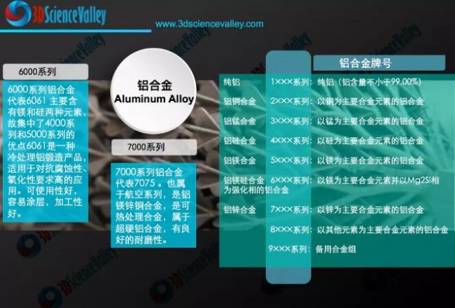 Aluminum alloy series
© 3D Science Valley White Paper
In this paper, the hot cracking mechanism of LPBF-treated 2195 Al-Li alloy was elucidated by a combination of experiments and theoretical calculations. The initiation, propagation and crack arrest processes of hot cracks are comprehensively discussed, which is of great significance for guiding process optimization.
Wu Shibo et al. of Harbin Institute of Technology established the relationship between microstructure evolution and high HCS for the first time, revealing the hot cracking mechanism. Observations from X-ray tomography revealed a 3D mesh of large interconnected cracks in the printed sample, extending layer by layer along the building direction from the layered cracks in the previous monorail. The study found that the cause of hot cracks was a stable liquid film and stress concentration. The segregation between Al6CuLi3 and α-Al matrix facilitates the formation of Al-Cu eutectic in the form of intercrystalline liquid film along high-angle grain boundaries. In addition, the interfacial layer (intradendritic liquid film) between Al2Cu and adjacent LiAlSi or AlCuMgAg was also found to exhibit reduced microcrack resistance inside the grains. The calculation results show that the higher the stability of the grain boundary liquid film, the higher the HCS at the grain boundary. In addition, the higher internal residual tensile stress provides the driving force for crack initiation and propagation. In conclusion, this work provides practical guidelines for optimizing the powder composition and processing steps of high-quality Al-Li alloys produced by LPBF.
1
The addition of Li and Cu significantly increases the hot crack susceptibility (HCS) of Al-Li alloys. Optimizing laser processing performance by adjusting process parameters is an important step in the fabrication of crack-free Al-Li components. Therefore, a series of single-track experiments were conducted to systematically investigate the effects of these process parameters. The single-track experimental results narrow the process parameter window to low laser power and low scan speed. According to the hot cracking mechanism in this paper, cracks can be suppressed by reducing the cooling rate and solidification rate in the final stage of the LPBF solidification process. Therefore, by preheating the substrate at 150 °C and reducing the scanning speed to 100 mm/s with a laser power of 200 W, a crack-free sample was successfully prepared, which is beneficial to reduce the temperature gradient, prolong the life of the molten pool, and prevent thermal cracking.
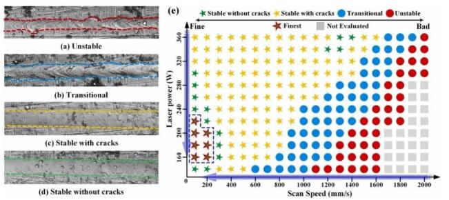 Fig. 1 Optimization of the process parameter window for monorail scanning: (a)-(d) Surface topography of typical monorail samples (e) Parameter optimization plot obtained from high-throughput monorail scanning
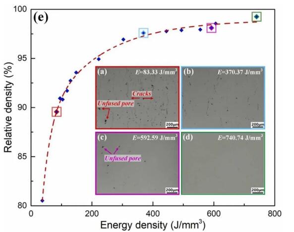 Fig. 2 Density analysis: (a)-(d) Typical cross-sectional OM images and; (e) Effect of energy density on relative density
2
The presence of lithium extends the solidification temperature range (STR) during LPBF. It was found that the solidification process of LPBF depends on the cooling rate, fast cooling rate leads to coarse columnar grains with crystallographic orientation <100> (perpendicular to MPB), and columnar epitaxy occurs on dendritic substrates in LPBF-treated cubic samples grow into nuclei. Notably, large STRs also enhance HCS during LPBF. To determine the precipitated phase of the LPBF-treated samples, α-Al matrix and T2 (Al6CuLi3) were detected in all XRD patterns of the printed samples as shown.
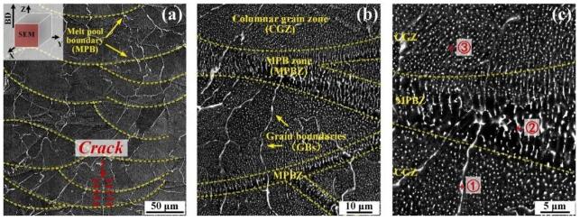 Fig. 3 SEM images of cubic samples: (a)-(c) BSE views of progressively enlarged microstructures
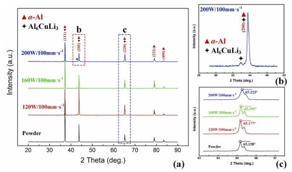 Fig. 4 XRD patterns: (a) powder and printed samples; (b) enlarged image of b area; (c) enlarged image of c area
3
The elemental distribution of lithium cannot be directly detected by EDS or WDS. Therefore, TEM observations play an important role in the characterization of Li-based precipitates, involving both the precipitate structure and chemical composition. In Al-Cu-Li alloys, in direct solidified alloys and in peak-aged or overaged alloys, the T2 phase tends to form at the HAGBs, and its formation ability mainly depends on the alloy composition and cooling rate. In the present case, the severe segregation of Cu and Li along the crystalline regions is responsible for the compositional range of the icosahedral phase. The rapid solidification properties during LPBF provide the driving force for the formation of coarse icosahedral phases along the GBs. At the same time, the formation of T2 phase inhibits the formation of other phases, such as theta phase. In addition to the T2 phase as a solidification reaction product, the segregation of solutes around the intergranular region also contributes to the low-melting Al-Cu eutectic at GBs during rapid solidification.
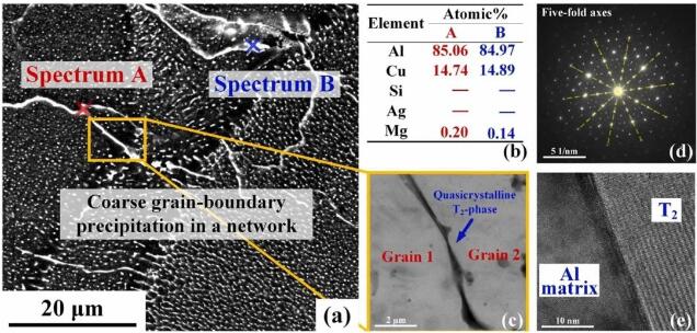 Figure 5 Phase identification of the quasicrystalline T2 phase: (a) BSE micrograph of the coarse GB phase in the network distribution; (b) EDS analysis results; (c) TEM morphology of the quasicrystalline phase; (d) with typical five-fold symmetry Sexual SAD pattern; (e) HRTEM image
 Figure 6 Elemental distribution and phase identification using TEM: (a) TEM bright-field micrograph; (bf) EDS mapping of Al, Cu, Si, Ag and Mg; (g) magnified image of region a; (h, i) Magnified images of the corresponding SAD patterns of regions a and b; (j) morphologies of δ´/β´, (k) corresponding SAD patterns of δ´/β´; (l) standard diffraction patterns along the <100> band axis
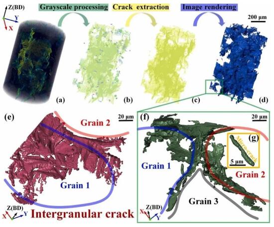 Fig. 7 Hot crack behavior of LPBF-treated samples: (a) typical XRM slice of the whole specimen; (b) macroscopic distribution of pores and cracks; (c, d) 3D images of networked large interconnected cracks; (e, f) ) fracture along the typical initial intergranular surface of GBs; (g) streak-like interfacial microcracks within the grains
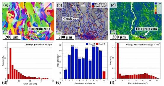 Fig. 8 EBSD results analysis of GBs on the longitudinal section of LPBF-treated Al-Li alloy: (a) IPF image; (b) GB distribution map of HAGBs and LAGBs; (c) KAM map showing strain concentration; (d) grain size distribution; (e) misorientation angle along the crack propagation path; (f) misorientation angle distribution
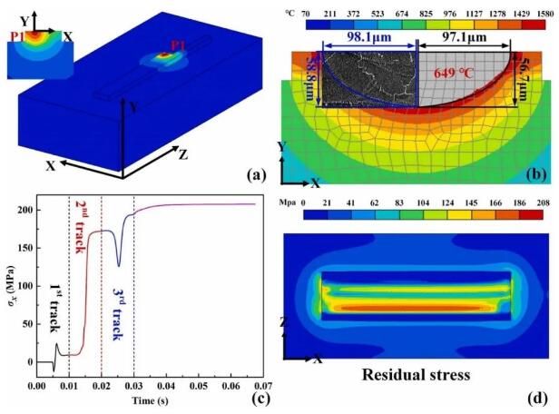 Fig. 9 Simulation results of temperature field and stress field in LPBF at P=200 W and v=100 mm/s: (a) temperature field; (b) experimental verification; (c) calculated thermal stress of X component at P1 ;(d) Residual stress distribution of X component
4
Hot cracks occur mainly along and around the intergranular region, and in previous work, it has been found that severe failures have been observed in alloys where most of the GBs are covered by a thin-film eutectic phase. Therefore, the alternating coarse T2 phase and thin-film Al-Cu eutectic phase along the grain boundaries increased the intergranular HCS of the prepared Al-Li alloy samples. When cracks are initiated along the GB region driven by the stress concentration, the interconnected precipitates will dissolve through the intergranular cracks. Ultimately, more complex and regular intergranular crack paths may appear and extend along the architectural direction, indicating a significantly lower crack propagation resistance compared to the situation inside the grain.
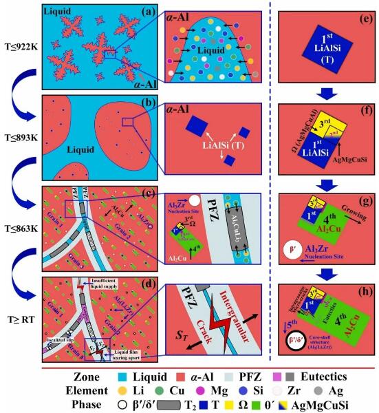 Fig.10 Schematic diagram of crystallization and element interdiffusion process: (a) α-Al liquid phase nucleation; (b) T-phase nucleation; (c) MgAgCuSi clusters, Ω-phase, θ′-phase intradendritic nucleation and T2 Interphase nucleation; (d) dissociated eutectic formation and intergranular crack initiation; (e)-(h) emphasis on the evolutionary sequence of intradendritic precipitation involving the most complex situations and times
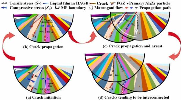 Fig. 11 Schematic diagram of crack initiation and propagation process: (a) crack initiation caused by tearing the liquid film under tensile stress; (b) crack propagation along GBs; (c) crack propagation to FGZ or continuous crack propagation along the dendrite growth direction (d) cracks that tend to converge together, resulting in large interconnected cracks with a 3D network structure
Knowing is deep, doing it is far. Based on a global network of superb manufacturing expert think tanks, 3D Science Valley provides the industry with an in-depth observation of additive and intelligent manufacturing from a global perspective. For more analysis in the field of additive manufacturing, follow the white paper series published by 3D Science Valley.
(responsible editor: admin)


0 Comments for “Thermal crack evolution and formation mechanism of 2195 Al-Li alloy in laser powder bed fusion printing”