“The simulation system of the single-chip motor speed measurement system uses the T1 counter in the single-chip microcomputer to count the speed pulses. Timer T1 works in the external event counting mode, counting speed pulses; T0 works in the timer mode. Read the count value once every 1 s. This value is the frequency of the pulse signal. According to formula (1), the motor speed can be calculated. The software system of the speed detection device mainly includes: the main program of the speed measurement, the data processing subroutine and the Display subroutine. After the microcontroller is powered on, the system enters the ready state. Initialize first, then read the pulse data for calculation, and display the speed on the LCD. Need this simulation and C
“
The simulation system of the single-chip motor speed measurement system uses the T1 counter in the single-chip microcomputer to count the speed pulses. Timer T1 works in the external event counting mode, counting speed pulses; T0 works in the timer mode. Read the count value once every 1 s. This value is the frequency of the pulse signal. According to formula (1), the motor speed can be calculated. The software system of the speed detection device mainly includes: the main program of the speed measurement, the data processing subroutine and the display subroutine. After the microcontroller is powered on, the system enters the ready state. Initialize first, then read the pulse data for calculation, and display the speed on the LCD. Fans who need this simulation and C language program can learn about it from the website in the upper left corner of the article.
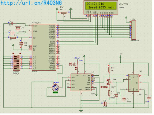
The simulation simulation of the single-chip motor speed measurement system adopts the frequency measurement method “M method” to measure the motor speed. That is, within a certain measurement time T, measure the number of pulses m1 generated by the pulse generator (instead of the input pulse) to measure the speed. The calculation formula is as follows: n=60m/TP, where: P- is generated by the pulse generator after one revolution of the shaft Number of pulses; n-speed unit: (revolutions/minute); T-timing time unit: (seconds). In this method, the measurement accuracy is due to the fact that the timing T and the pulse cannot guarantee strict synchronization, and whether the complete cycle of the external pulse can be measured within T, and the quantization error of 1 pulse may be generated. Therefore, in order to improve the measurement accuracy, T must have a long enough time. The timing time can be preset according to the conditions of the measurement object. If the setting time is too long, the accuracy can be improved. However, when the speed is fast, the number of pulses counted increases (when the number of holes in the code wheel is fixed), which limits the range of speed measurement. If the set time is too short, the measurement accuracy will be affected to a certain extent.
The software design idea of the speed part: The P3.5 port of the AT89S52 single-chip microcomputer receives the signal of the sensor. The circuit is composed of display circuit, AT89S52 single-chip microcomputer, single-chip clock circuit, reset circuit, etc. For the interrupt service routine INT0, what the software needs to solve is the coordination of the counting of the timer T0 and the external counter T1. Due to the wide range of measured speed, both low speed and high speed should be taken into account. Software workflow: The sensor detects the number of pulses of one revolution of the motor, which is sent to the single-chip microcomputer from the P3.5 port of the single-chip microcomputer, and counted by the internal counter T1 of the single-chip microcomputer When starting counting, send a signal TR0=1. When the internal timer T0 starts, TH0 and TL0 set the initial value to 0.
The Links: EL640480-AG1 1DI-480A-055
0 Comments for “How to design the simulation system of C51 single chip microcomputer in the measurement of motor speed”