“The PWM control method is widely used in various control systems, but the adjustment of the pulse width is generally realized by hardware.Such as using a PWM controller or adding a PWM circuit to the system[1]And so on, the cost is high, the response speed is slow, and there are compatibility problems between the PWM controller and the system. In addition, the signal sampling in the control system is usually done by the A/D converter. Therefore, when the detection accuracy is high, the conditioning circuit is complicated, and because the number of A/D bits is high, the cost of the designed system remains high. .
“
The PWM control method is widely used in various control systems, but the adjustment of the pulse width is generally realized by hardware.Such as using a PWM controller or adding a PWM circuit to the system[1]And so on, the cost is high, the response speed is slow, and there are compatibility problems between the PWM controller and the system. In addition, the signal sampling in the control system is usually done by the A/D converter. Therefore, when the detection accuracy is high, the conditioning circuit is complicated, and because the number of A/D bits is high, the cost of the designed system remains high. .
This article takes the temperature control system as an example, and introduces the method of using the timer Time_A in the new single-chip microcomputer MSP430F413 produced by MOTOROLA Company to design the temperature sampling and realize the PWM adjustment with the amount of time. In order to achieve high-precision measurement and control of the control system with a small number of peripheral circuits, on the one hand, time sampling is used to obtain 12-bit high precision while saving 1 piece of A/D; on the other hand, in timing The PWM adjustment is completely realized by software in the interrupt, so as to facilitate the communication and Display of the data. The system can solve the real-time online calculation and calculation accuracy problems of waveform generation within the interrupt, and can accurately and real-time calculate the pulse width at the set frequency.
1 MCU MSP430F413 and timer
The MSP430 series single chip microcomputer F413 has certain characteristics in ultra-low power consumption and functional integration, which can greatly reduce the complexity of peripheral circuits. Its real-time processing capability and various peripheral modules make it applicable to multiple low power consumption field[2]. The general 16-bit timer Timer_A in MSP430F413 has the following main functional modules.
(1) A counter that can continuously count up to a predetermined value and return to 0.
(2) The software can select the clock source.
(3) 5 capture/compare registers, each with an independent capture event.
(4) 5 output modules to support the needs of pulse width modulation.
The bits of the timer control register TACTL can control the configuration of Timer_A and define the basic operation of the 16-bit timer. You can select the original frequency or the divided input clock source and 4 working modes. There are also clear functions and overflow interrupt control bits. The operation of the five capture/compare registers CCRx is the same, and they are configured through their respective control registers CCTLx.
2 The realization principle of time sampling and PWM control
Take the temperature control system as an example, introduce the method of using timer to realize signal sampling and PWM control. The temperature control system includes a single-chip microcomputer, temperature measurement circuit, load drive circuit and power supply control, low voltage detection and display circuit and other peripheral parts.
The main I/O ports used to measure and control temperature in the single-chip MSP430F413 are:
P1.0: Output 50Hz square wave, used to generate triangle wave.
P1.2: Drive temperature control actuator, 2kHz square wave PWM output.
P2.0: Pulse width capture.
2.1 The interrupt setting of the MCU port
The 50Hz square wave output, PWM output and input capture of the temperature control system are all realized by timing interrupts. These 3 interrupts are caused by the peripheral modules of the P0, P1, and P2 ports, respectively, and belong to external maskable interrupts. During initialization, interrupt settings for these 3 I/O ports, and the Time_A control register TACTL settings, including the input signal divided by 2 and the selection of the auxiliary clock ACLK. After defining the capture/compare register, re-assign TACTL, start the timer, and start counting up continuously.
2.2 Pulse width capture to achieve temperature sampling
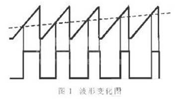
The temperature measurement circuit converts the temperature value into a voltage value. At the same time, the 50Hz square wave generated by the single-chip microcomputer is transformed by the capacitor charging and discharging circuit to obtain a triangular wave of the same frequency. The waveform changes are shown in Figure 1.
By setting the mode bit in CCTLx, the corresponding capture/compare register CCRx can be set to capture mode for precise positioning of time events. If the trigger edge of the selected pulse occurs on the selected input pin, the value of the timer count will be copied to CCRx. According to this principle, P2.0 is selected as the input pin, and CCTL2 is set as the capture mode. After the measured temperature value is converted from an analog quantity into a pulse by the measuring circuit, P2.0 captures the falling edge of the pulse and enters the interrupt T2. Get the number of pulses per unit time consistent with the temperature value and store it in CCR2 for further processing.
In this way, the system completes the analog-to-digital conversion without using an A/D converter. Because the clock of the single-chip microcomputer is accurate, and the amount of time is a relatively high-precision amount, but in this system, the temperature sampling with the amount of time can obtain 12-bit high precision. At the same time, the 50Hz pulse can be used to greatly eliminate the power frequency interference. All of these provide the necessary conditions for precise temperature control.
2.3 The inherent principle of PWM signal
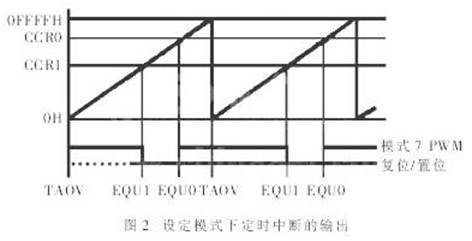
The capture/compare registers CCR0 and CCR1 are defined as comparison modes, and their output units OUT0 and OUT1 correspond to the MCU pins P1.0 (TA0) and P1.2 (TA1) respectively. After entering the comparison mode, if the count value of the timer CCRx is the value in the comparison register x, the comparison signal EQUx is output to the output unit OUTx, and the signal is set, reset or inverted according to the selected mode. Among them: set EQU0 to invert the OUT0 signal, the signal clock is synchronized with the timer clock, so that a 50Hz square wave signal can be obtained on the P1.0 pin; set the EQU1 output mode to PWM reset/set.
The output of the timer interrupt in the setting mode is shown in Figure 2. According to the set PWM reset/set mode, if the CCR1 counter overflows, EQU1 resets OUT1; if the CCR0 counter overflows, EQU0 sets OUT1. Utilize the difference between CCR0 and CCR1 to count the starting point to realize the duty cycle change, thereby completing the PWM output on P1.2. The adjustment of the duty cycle of the system is realized by changing the base of CCR1. When the timer clock is 2MHz and the count value of CCR1 and CCR0 is 1,000, a PWM output frequency of 2kHz can be obtained. The load drive circuit amplifies and filters the PWM signal output from the P1.2 pin of the single-chip microcomputer to drive high-power actuators.
3 software design
3.1 System main program
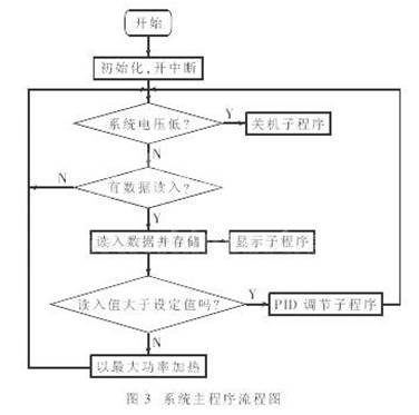
The main program includes system initialization, timer initialization, temperature sampling value reading, load driving and display, etc. The temperature value sampling and PWM output of the system are all completed in the timing interrupt, and the duty cycle of the PWM output pulse is obtained by the PID algorithm. The main program flowchart of the system is shown as in Fig. 3.
3.2 PID pulse width adjustment
The modulation of the pulse width of the system is realized by PID algorithm. According to the algorithm principle, this system designs a set of PID algorithm which is completely realized by software, and completes the parameter self-tuning in the control process. The control process of PID adjustment: The single-chip microcomputer reads the actual temperature Tn in digital form, and then compares it with the set temperature Tg to get the difference en=Tn-Tg. According to the positive and negative sum of en, the PID formula is called, and the calculation is The duty cycle of the output voltage Δun is consistent, and the temperature rise and fall are adjusted, and the optimal conditions are found at the same time to change the PID parameters.
Incremental PID control algorithm output[3]:
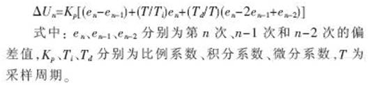
The PID adjustment program is directly written into the single-chip microcomputer, and the base value of the counter CCR1 is changed according to the obtained value, thereby changing the duty cycle of the output pulse to achieve the purpose of adjusting the PWM.
3.3 Timed interrupt
The regular interrupt subroutine flow is shown as in Fig. 4. The crystal oscillator frequency used by the system is 2MHz, and the function of the T0 interrupt is to obtain a square wave with a frequency of 50 Hz and a duty cycle of 90% to generate a triangle wave and check whether there is any missing data in one cycle. T0 mode overflow flips to high level, and the output comparison interval is 18ms. Among them, CCR0 adds the PWM modulus, which is the difference between CCR0 and CCR1, used to generate the pulse width required for output.
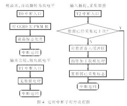
What is processed in the T1 interrupt is the PWM output of the control port, and it is checked whether the data is collected repeatedly in 1 cycle, the T1 output comparison produces a low level, and the output comparison interval is 20ms. T2 interrupts to capture the pulse width of the temperature measurement port to obtain the measured temperature value.
4 Conclusion
The method of using the timer Time_A in the microcontroller MSP430F413 for temperature sampling and realizing PWM adjustment can be widely used in microcontrollers with port capture functions. Compared with the traditional method, it can not only simplify the hardware structure of the measurement and control circuit, but also can easily establish a man-machine interface, realize the use of software to adjust the parameters, and make the control more accurate, real-time, and reliable. After experiments, the method is applied to the temperature control system to obtain the expected precise PWM adjustment waveform. This method can also be used in other single-chip control systems.
The Links: 1DI200Z-140 6MBI8L-120
0 Comments for “Realize signal sampling and PWM control by using single-chip timer”